|
[Go to TOC]
RADIATION PATTERNS
The radiation pattern is a graphical depiction of the relative field strength transmitted from or received by
the antenna. Antenna radiation patterns are taken at one frequency, one polarization, and one plane cut. The patterns
are usually presented in polar or rectilinear form with a dB strength scale. Patterns are normalized to the maximum
graph value, 0 dB, and a directivity is given for the antenna. This means that if the side lobe level from the radiation
pattern were down -13 dB, and the directivity of the antenna was 4 dB, then the sidelobe gain would be -9 dB.
 Figures
1 to 14 on the pages following depict various antenna types and their associated characteristics. The patterns depicted
are those which most closely match the purpose for which the given shape was intended. In other words, the radiation
pattern can change dramatically depending upon frequency, and the wavelength to antenna characteristic length ratio.
See section 3-4. Antennas are designed for a particular frequency. Usually the characteristic length is a multiple
of λ/2 minus 2-15% depending on specific antenna characteristics. Figures
1 to 14 on the pages following depict various antenna types and their associated characteristics. The patterns depicted
are those which most closely match the purpose for which the given shape was intended. In other words, the radiation
pattern can change dramatically depending upon frequency, and the wavelength to antenna characteristic length ratio.
See section 3-4. Antennas are designed for a particular frequency. Usually the characteristic length is a multiple
of λ/2 minus 2-15% depending on specific antenna characteristics.
The gain is assumed to mean directional gain of the antenna compared to an isotropic radiator transmitting to
or receiving from all directions.
The half-power (-3 dB) beamwidth is a measure of the directivity of the antenna.
Polarization, which is the direction of the electric (not magnetic) field of an antenna is another important
antenna characteristic. This may be a consideration for optimizing reception or jamming.
The bandwidth is a measure of how much the frequency can be varied while still obtaining an acceptable VSWR (2:1
or less) and minimizing losses in unwanted directions. See Glossary, Section 10.
A 2:1 VSWR corresponds to a 9.5dB (or 10%) return loss - see Section 6-2.
Two methods for computing antenna bandwidth are used:
Narrowband by %,
 where FC = Center frequency
Broadband by ratio,

An antenna is considered broadband if FU / FL > 2. The table at the right shows the equivalency of the two,
however the shaded values are not normally used because of the aforementioned difference in broadband/narrowband.

For an object that experiences a plane wave, the resonant mode is achieved when the dimension of the object
is λ/2, where n is an integer. Therefore, one can treat the apertures shown in the figure below as half wave length
dipole antennas for receiving and reflecting signals. More details are contained in section 8-4.The following
lists antenna types by page number. The referenced page shows frequency limits, polarizations, etc.
| 4 arm conical spiral |
3-3.6 |
log periodic |
3-3.8 |
| alford loop |
3-3.4 |
loop, circular |
3-3.4 |
| aperture synthesis |
3-3.8 |
loop, alfred |
3-3.4 |
| array |
3-3.8 |
loop, square |
3-3.4 |
| axial mode helix |
3-3.5 |
luneberg lens |
3-3.9 |
| biconical w/polarizer |
3-3.6 |
microstrip patch |
3-3.9 |
| biconical |
3-3.6 |
monopole |
3-3.3 |
| cavity backed circuit fed slot |
3-3.9 |
normal mode helix |
3-3.5 |
| cavity backed spiral |
3-3.5 |
parabolic |
3-3.7 |
| circular loop |
3-3.4 |
patch |
3-3.9 |
| conical spiral |
3-3.5 |
reflector |
3-3.9 |
| corner reflector |
3-3.9 |
rhombic |
3-3.3 |
| dipole array, linear |
3-3.8 |
sinuous, dual polarized |
3-3.6 |
| dipole |
3-3.3 |
slot, guide fed |
3-3.9 |
| discone |
3-3.4 |
slot, cavity backed |
3-3.9 |
| dual polarized sinuous |
3-3.6 |
spiral, 4 arm conical |
3-3.6 |
| guide fed slot |
3-3.9 |
spiral, conical |
3-3.5 |
| helix, normal mode |
3-3.5 |
spiral, cavity backed |
3-3.5 |
| helix, axial mode |
3-3.5 |
square loop |
3-3.4 |
| horn |
3-3.7 |
vee |
3-3.3 |
| linear dipole array |
3-3.8 |
yagi |
3-3.8 |
 |
 |
MONOPOLE Polarization: Linear Vertical as shown
Typical Half-Power Beamwidth 45 deg x 360 deg
Typical Gain: 2-6 dB at best
Bandwidth: 10% or 1.1:1
Frequency Limit Lower: None Upper: None
Remarks: Polarization changes to horizontal if rotated to horizontal
|
 |
 |
λ/2 DIPOLE Polarization: Linear Vertical as shown
Typical Half-Power Beamwidth 80 deg x 360 deg
Typical Gain: 2 dB
Bandwidth: 10% or 1.1:1
Frequency Limit Lower: None Upper: 8 GHz (practical limit)
Remarks: Pattern and lobing changes significantly with L/f. Used as a gain reference < 2 GHz.
|
Figure 1
 |
 |
VEE Polarization: Linear Vertical as shown
Typical Half-Power Beamwidth 60 deg x 60 deg
Typical Gain: 2 to 7 dB
Bandwidth: "Broadband"
Frequency Limit Lower: 3 MHz Upper: 500 MHz (practical limits)
Remarks: 24 kHz versions are known to exist. Terminations may be used to reduce backlobes.
|
 |
 |
RHOMBIC Polarization: Linear Vertical as shown
Typical Half-Power Beamwidth 60 deg x 60 deg
Typical Gain: 3 dB
Bandwidth: "Broadband"
Frequency Limit Lower: 3 MHz Upper: 500 MHz
Remarks: Termination resistance used to reduce backlobes.
|
Figure 2
 |
 |
CIRCULAR LOOP (small) Polarization: Linear Horizontal as shown
Typical Half-Power Beamwidth: 80 deg x 360 deg
Typical Gain: -2 to 2 dB
Bandwidth: 10% or 1.1:1
Frequency Limit: Lower: 50 MHz Upper: 1 GHz
|
 |
 |
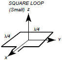
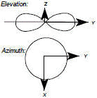
SQUARE LOOP
Polarization: Linear Horizontal as shown
Typical Half-Power Beamwidth: 100 deg x 360 deg
Typical Gain: 1-3 dB
Bandwidth: 10% or 1.1:1
Frequency Limit: Lower: 50 MHz Upper: 1 GHz
|
Figure 3
 |
 |
DISCONE Polarization: Linear Vertical as shown
Typical Half-Power Beamwidth: 20-80 deg x 360 deg
Typical Gain: 0-4 dB
Bandwidth: 100% or 3:1
Frequency Limit: Lower: 30 MHz Upper: 3 GHz
|
 |
 |
ALFORD LOOP Polarization: Linear Horizontal as shown
Typical Half-Power Beamwidth: 80 deg x 360 deg
Typical Gain: -1 dB
Bandwidth: 67% or 2:1
Frequency Limit: Lower: 100 MHz Upper: 12 GHz |
Figure 4
 |
 |
AXIAL MODE HELIX Polarization: Circular Left hand as shown
Typical Half-Power Beamwidth: 50 deg x 50 deg
Typical Gain: 10 dB
Bandwidth: 52% or 1.7:1
Frequency Limit Lower: 100 MHz Upper: 3 GHz
Remarks: Number of loops >3
|
 |
 |
NORMAL MODE HELIX Polarization: Circular - with an ideal pitch to diameter ratio.
Typical Half-Power Beamwidth: 60 deg x 360 deg
Typical Gain: 0 dB
Bandwidth: 5% or 1.05:1
Frequency Limit Lower: 100 MHz Upper: 3 GHz
|
Figure 5
 |
 |
CAVITY BACKED SPIRAL (Flat Helix) Polarization: Circular Left hand as shown
Typical Half-Power Beamwidth: 60 deg x 90 deg
Typical Gain: 2-4 dB
Bandwidth: 160% or 9:1
Frequency Limit: Lower: 500 MHz Upper: 18 GHz
|
 |
 |
CONICAL SPIRAL Polarization: Circular Left hand as shown
Typical Half-Power Beamwidth: 60 deg x 60 deg
Typical Gain: 5-8 dB
Bandwidth: 120% or 4:1
Frequency Limit: Lower: 50 MHz Upper: 18 GHz
|
Figure 6
 |
 |
4 ARM CONICAL SPIRAL Polarization: Circular Left hand as shown
Typical Half-Power Beamwidth: 50 deg x 360 deg
Typical Gain: 0 dB
Bandwidth: 120% or 4:1
Frequency Limit: Lower: 500 MHz Upper: 18 GHz
|
 |
 |
DUAL POLARIZED SINUOUS Polarization: Dual vertical or horizontal or dual Circular right
hand or left hand with hybrid
Typical Half-Power Beamwidth: 75 deg x 75 deg
Typical Gain: 2 dB
Bandwidth: 163% or 10:1
Frequency Limit: Lower: 500 MHz Upper: 18 GHz
|
Figure 7
 |
 |
BICONICAL Polarization: Linear, Vertical as shown
Typical Half-Power Beamwidth: 20-100 deg x 360 deg
Typical Gain: 0-4 dB
Bandwidth: 120% or 4:1
Frequency Limit: Lower: 500 MHz Upper: 40 GHz
|
 |
 |
BICONICAL W/POLARIZER Polarization: Circular, Direction depends on polarization
Typical Half-Power Beamwidth: 20-100 deg x 360 deg
Typical Gain: -3 to 1 dB
Bandwidth: 100% or 3:1
Frequency Limit: Lower: 2 GHz Upper: 18 GHz
|
Figure 8
 |
 |
HORN Polarization: Linear
Typical Half-Power Beamwidth: 40 deg x 40 deg
Typical Gain: 5 to 20 dB
Bandwidth: If ridged: 120% or 4:1 If not ridged: 67% or 2:1
Frequency Limit: Lower: 50 MHz Upper: 40 GHz
|
 |
 |
HORN W/POLARIZER Polarization: Circular, Depends on polarizer
Typical Half-Power Beamwidth: 40 deg x 40 deg
Typical Gain: 5 to 10 dB
Bandwidth: 60% or 2:1
Frequency Limit: Lower: 2 GHz Upper: 18 GHz
|
Figure 9
 |
 |
PARABOLIC (Prime) Polarization: Takes polarization of feed
Typical Half-Power Beamwidth: 1 to 10 deg
Typical Gain: 20 to 30 dB
Bandwidth: 33% or 1.4:1 limited mostly by feed
Frequency Limit: Lower: 400 MHz Upper: 13+ GHz
|
 |
 |
PARABOLIC Polarization: Takes polarization of feed
Typical Half-Power Beamwidth: 1 to 10 deg
Typical Gain: 20 to 30 dB
Bandwidth: 33% or 1.4:1
Frequency Limit: Lower: 400 MHz Upper: 13+ GHz
|
Figure 10
 |
 |
YAGI Polarization: Linear Horizontal as shown
Typical Half-Power Beamwidth 50 deg X 50 deg
Typical Gain: 5 to 15 dB
Bandwidth: 5% or 1.05:1
Frequency Limit: Lower: 50 MHz Upper: 2 GHz
|
 |
 |
LOG PERIODIC Polarization: Linear
Typical Half-Power Beamwidth: 60 deg x 80 deg
Typical Gain: 6 to 8 dB
Bandwidth: 163% or 10:1
Frequency Limit: Lower: 3 MHz Upper: 18 GHz
Remarks: This array may be formed with many shapes including dipoles or toothed arrays.
|
Figure 11
 |
 |
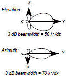
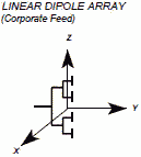
LINEAR DIPOLE ARRAY (Corporate Feed) Polarization: Element dependent Vertical as shown
Typical Half-Power Beamwidth: Related to gain
Typical Gain: Dependent on number of elements
Bandwidth: Narrow
Frequency Limit: Lower: 10 MHz Upper: 10 GHz
|
 |
 |
APERATURE SYNTHESIS All characteristics dependent on elements
Remarks: Excellent side-looking, ground mapping where the aircraft is a moving linear element.
|
Figure 12
 |
 |
CAVITY BACKED CIRCUIT FEED SLOT (and microstrip patch) Polarization: Linear, vertical as shown
Typical Half-Power Beamwidth: 80 deg x 80 deg
Typical Gain: 6 dB
Bandwidth: Narrow
Frequency Limit: Lower: 50 MHz Upper: 18 GHz
Remarks: The feed line is sometimes separated from the radiator by a dielectric & uses capacitive coupling.
Large conformal phased arrays can be made this way.
|
 |
 |
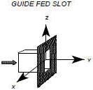
GUIDE FED SLOT Polarization: Linear,
Typical Half-Power Beamwidth Elevation: 45-50E Azimuth: 80E
Typical Gain: 0 dB
Bandwidth: Narrow
Frequency Limit: Lower: 2 GHz Upper: 40 GHz
Remarks: Open RF Waveguide
|
Figure 13
 |
 |
CORNER REFLECTOR Polarization: Feed dependent
Typical Half-Power Beamwidth 40 deg x variable
Typical Gain: 10 dB above feed
Bandwidth: Narrow
Frequency Limit Lower: 1 GHz Upper: 40 GHz
Remarks: Typically fed with a dipole or collinear array.
|
 |
 |
LUNEBURG LENS (also LUNEBERG) Polarization: Feed dependent
Typical Half-Power Beamwidth: System dependent
Typical Gain: System dependent
Bandwidth: Narrow
Frequency Limit Lower: 1 GHz Upper: 40 GHz
Remarks: Variable index dielectric sphere.
|
Figure 14
Table of Contents for Electronics Warfare and Radar Engineering Handbook
Introduction |
Abbreviations | Decibel | Duty
Cycle | Doppler Shift | Radar Horizon / Line
of Sight | Propagation Time / Resolution | Modulation
| Transforms / Wavelets | Antenna Introduction
/ Basics | Polarization | Radiation Patterns |
Frequency / Phase Effects of Antennas |
Antenna Near Field | Radiation Hazards |
Power Density | One-Way Radar Equation / RF Propagation
| Two-Way Radar Equation (Monostatic) |
Alternate Two-Way Radar Equation |
Two-Way Radar Equation (Bistatic) |
Jamming to Signal (J/S) Ratio - Constant Power [Saturated] Jamming
| Support Jamming | Radar Cross Section (RCS) |
Emission Control (EMCON) | RF Atmospheric
Absorption / Ducting | Receiver Sensitivity / Noise |
Receiver Types and Characteristics |
General Radar Display Types |
IFF - Identification - Friend or Foe | Receiver
Tests | Signal Sorting Methods and Direction Finding |
Voltage Standing Wave Ratio (VSWR) / Reflection Coefficient / Return
Loss / Mismatch Loss | Microwave Coaxial Connectors |
Power Dividers/Combiner and Directional Couplers |
Attenuators / Filters / DC Blocks |
Terminations / Dummy Loads | Circulators
and Diplexers | Mixers and Frequency Discriminators |
Detectors | Microwave Measurements |
Microwave Waveguides and Coaxial Cable |
Electro-Optics | Laser Safety |
Mach Number and Airspeed vs. Altitude Mach Number |
EMP/ Aircraft Dimensions | Data Busses | RS-232 Interface
| RS-422 Balanced Voltage Interface | RS-485 Interface |
IEEE-488 Interface Bus (HP-IB/GP-IB) | MIL-STD-1553 &
1773 Data Bus | This HTML version may be printed but not reproduced on websites.
|


 Figures
1 to 14 on the pages following depict various antenna types and their associated characteristics. The patterns depicted
are those which most closely match the purpose for which the given shape was intended. In other words, the radiation
pattern can change dramatically depending upon frequency, and the wavelength to antenna characteristic length ratio.
See section 3-4. Antennas are designed for a particular frequency. Usually the characteristic length is a multiple
of λ/2 minus 2-15% depending on specific antenna characteristics.
 where FC = Center frequency


