|
|||||||||||||
 |
|||||||||||||
Build This Novice CW Transmitter
|
|||||||||||||
Even though this CW (continuous wave, for sending Morse code) transmitter circuit was published in 1955 in Popular Electronics magazine, it is still legal for today's Amateur radio operator. Portions of the 40-meter and 80-meter bands are still reserved exclusively for CW operation. As of 2021, the 40-meter band (7.025-7.125 MHz) and the 80-meter band (3.525-3.600 MHz) are both reserved for CW for Hams holding either Novice (no longer issued) or Technician licenses. Additionally, the 15-meter band (21.025-21.200 MHz) and the 2-meter band (144.0-144.1 MHz) have CW-only areas. That is different than the frequencies given in the article, so beware if you are tempted to throw one together for old time's sake. The value for XTAL will need to be changed accordingly. Both bands are a bit lower than shown here, so you might need to tweak the tuning elements a tad as well. If you are not a designer, you would be better off just finding a newer circuit that is already configured for the new bands. Build This Novice CW Transmitter
The beginner in ham radio with a novice license should become active as quickly as possible with a low-powered telegraph (CW) transmitter. Operating this rig as often as he can will give valuable on-the-air experience in handling the code and in correct operating procedure. The best way to learn is by doing. Note that two different coils must be built to cover both the 40 and 80 meter bands. A novice's first transmitter should be both simple and inexpensive. A good idea is to use the lower frequency bands. There, the new operator usually will find more "rag chewers" and local contacts than on the higher frequency long-distance bands. In the 80-meter band, novice CW operation is permitted between 3700 and 3750 kc. In the 40-meter band, the novice's territory is 7175 to 7200 kc. Crystal control must be used.
To reduce expense and to keep hum-producing power equipment off the transmitter chassis, no power supply is built into the transmitter. This allows the experimenter to use any external unit supplying 250 volts d.c. at 50 to 65 ma. and 6.3 volts - a.c, or d.c. at 1 ampere. Most experimenters keep a small power supply of this type on hand for general use. Such units also can be bought cheaply in surplus. The necessary a.c. and d.c. voltages often can be drawn from the receiver used with the transmitter. For portable use, a 6-volt storage battery can be used in conjunction with 180 to 225 volts of "B" batteries or a vibrator-type 250-volt supply. Transmitter Circuit
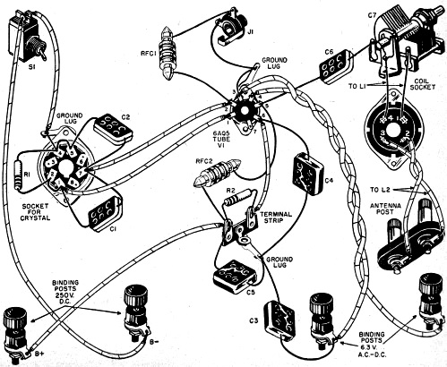
A shunt-fed plate circuit is employed. That is, the output (tank) circuit, consisting of coil L1 and tuning capacitor C7, is isolated from the d.c. plate voltage of the tube by capacitor C6. This arrangement keeps d.c. voltage off the coil and protects the operator from electric shock. Nevertheless, switch S1 should be thrown to its "off" position before changing coils, since the r.f. voltage may burn the fingers quite painfully just the same. The key is plugged into jack J1 The two "Antenna" binding post terminals are connected to the antenna. Construction An 8-pin octal tube socket is mounted on the left end of the chassis to hold the crystal. Socket pins 1 and 4 receive the pins of the crystal holder, while other pins of this socket are used as tie points for resistor R1 capacitors C1, and C2, and leads. A 1 1/8" hole is needed for the crystal socket.
Directly behind this coil socket is the insulated 2-terminal binding post block for antenna connections. This block assembly is a National Type FWH. The insulating blocks fit into 1/2" -diameter holes drilled 3/4" apart on centers. Switch S1 jack J1 and tuning capacitor C7 are mounted, from left to right, without insulation, along the front lip of the chassis. The jack and tuning capacitor require 3/8" mounting holes. The toggle switch (S1) requires a 1/2" hole. Four insulated binding posts are mounted along the rear lip of the chassis for connections to 6.3 volts and 250 volts. The two coils are wound on conventional 1" -diameter, 4-pin, phenolic plug-in forms. The accompanying coil table gives instructions for winding these coils. Each consists of a main coil L1 and a coupling coil L2 The ends of L1 are fed into the two large pins of the form and soldered. The ends of L2 are fed into the two small pins and soldered. For adjusting the transmitter, make a test lamp by forming a 1 1/4" -diameter loop of insulated hookup wire and soldering its two ends to the terminals of a 6-volt pilot lamp. Obtain an 80-meter crystal on any frequency between 3700 and 3750 kc, and a 40-meter crystal on any frequency between 7175 and 7200 kc. Several crystals in each frequency range will allow movement "around the band" when interference sets in.
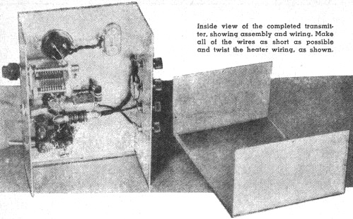
Operating Instructions To place the transmitter into operation: (a) Plug in an 80-meter crystal. (b) Plug in the 80-meter coil. (c) Connect the 6.3 v. and 250 v. power supply. (d)·Throw the switch S1 to "on." (e) When the tube has heated, plug the key into jack J1. (f) Hold the loop of the test lamp over the top of the coil. (g) Depress the key; while holding it, adjust tuning capacitor C7 until the lamp lights. Back away with the lamp if it is burning too brightly. (h) Tune capacitor C7 for brightest lamp response. (i) Taking care that the key is in its up or "off" position, connect the antenna leads to the "Antenna" binding posts. (j) Again, close the key, hold the lamp loop near the coil, and retune capacitor C7 for brightest lamp response. When wiring the transmitter follow both schematic and pictorial diagrams closely. The transmitter now is tuned-up on 80 meters, and is ready to go. The signal may be monitored for smoothness by listening to it with a receiver (minus antenna) or on a c w monitor. To tune up on 40 meters, repeat the entire process with a 40-meter crystal and the 40-meter coil plugged in. If you do not have any of the power sources mentioned in the early part of this article, you can use this transmitter with a power supply to be described in the next issue of POPULAR ELECTRONICS END
Posted October 21, 2021 |
|||||||||||||
 |
|||||||||||||
|
|||||||||||||


|
||||||||||||||||||||||||||||||||||||


