|
Not having a full collection
of magazines is a real disadvantage when multiple part stories are published and
some editions are missing. Such is the case here with Milton Kiver's series on "Theory
and Application of UHF" in Radio News magazine. I do have other parts of
the series, but they have not been posted on RF Cafe yet. However, each installment
is pretty much independent of the others. This month's topic is on the fundamental
theory of electrical potential and force. The name "Maxwell" is mentioned, but not
in the way that strikes fear in the heart of engineering students being introduced
to the integral and differential forms of his
eponymous equations
(I know first-hand), so it's safe to keep reading.
Gauss's Law get
honorable mention as well. First semester physics books cover the same material,
but since you might not have one handy, here you go.
Eleven installments appeared in the following issues: Part 1: December 1943
(p35), 2: January 1944 (p32), 3: March 1944 (p41), 4: April 1944 (p46),
5: May 1944 (p50), 6: August 1944 (p53), 7:
October 1944
(p58), 8: December
1944 (56), 8: February 1945 (p58), 10: April 1945 (p57), 11: June 1945 (p57). I hope
to eventually procure those editions and post the articles.
Theory and Application of U.H.F. - Part 10

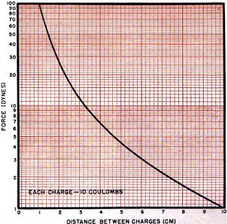
Fig. 1 - Showing the relationship of force vs. distance
between electrical charges.
By Milton S. Kiver
Part 10. An explanation of the importance of the electric field theory of Maxwell's
equations in describing u.h.f. phenomena. A subsequent article will cover a similar
explanation based upon the magnetic principles.
The name of Maxwell seems to be ever present in describing ultra-high-frequency
phenomena and this perhaps, is as it should be, since without his work it might
have taken a great deal longer to fill out the ideas on wave propagation.
The set of equations that form the basis for the electromagnetic theory are called
Maxwell's equations, although he is not solely responsible for most of them. All
these equations are expressed either in ordinary differential form or compactly
placed by means of vector analysis. Neither will be used here since it is the avowed
purpose of these article to use very little mathematics, so (with apologies to Maxwell)
an attempt will be made to discuss these important relations without the benefit
of the exact science. With this explanation as a background it should be much easier
to comprehend some of the properties of wave guides, cavity resonators, antennas,
and any other device that depends for its action on the above-mentioned law.
Maxwell's equations are generalized statements on the behavior of electric and
magnetic fields. The electric laws are based on the observed behavior of the electron
and the influence it exerts on other nearby electrons. It would have been just as
easy to have based all our findings on the proton (positive charge) behavior, but
since the electron is the more mobile of the two it is easier to deal with its properties.
For the magnetic laws it is necessary to go back to the properties of a magnet and
see its actions and reactions when brought near other substances that are affected
by it. When all these important facts are tabulated, there are four (sometimes given
as five) statements that form the starting point. These four (or five) equations
are known as Maxwell's equations.
Now to see just what these equations mean. They set down a set of rules by which
the science of electromagnetics has been developed. As long as these rules are followed,
all is fair; but if any deviations are introduced, then the fundamental principles
of the science are being ignored and something else is now being engaged in; another
game - so to speak. There is nothing wrong in modifying the rules if it is found
that experience dictates such a change. But so far Maxwell's equations have predicted
all the observed results so it is safe to assume that they are entirely correct
and no attempt should be made to change any of their forms.
These equations may be looked upon as four walls to keep the players within certain
confines. While in these boundaries they may make other limitations, such as having
the electric or magnetic fields restricted to one direction, but this is still within
the game since the general rules are in no way being altered. The rules are just
not being used to their fullest extent - that is all. Since the equations work in
one, two, or three dimensions, it is possible to use the above restrictions and
still arrive at correct results.
Fundamental Electrical Theory

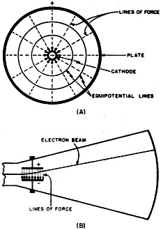
Fig. 2 - Indicating the distribution of force about an electric
charge by means of equipotential lines.

Fig. 3 - The use of lines of force and equipotential lines
in radio tubes.
Before any discussion of the above equations will be undertaken, it would be
advisable to review the foundations of all electric and magnetic theory. The electric
field will be dealt with first. Any electric charge, such as an electron, exerts
a force upon other charges near itself. This force, while being just as much a force
as the gravitational pull or the force exerted by a machine, does not apply to every
material body in the universe but only to other electric charges. If these other
charges are positive, the force is one of attraction while if they are negative,
it is a repelling force. Now, for many people the idea of just showing a charge
without indicating its force was rather hard to understand, so whenever an electric
charge is shown, lines radiating away from this charge are also drawn and these
lines are called lines of force. They are the pictorial representations of what
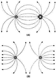
cannot be seen but what is quite definitely there, namely, the force itself. Fig. 5
shows these various lines, both for attraction and repulsion.
In addition to the representation of the electric lines of force, as in the above
figure, it is also possible to indicate the distribution of electric forces as in
Fig. 2. Here instead of lines of force, we have all the points that have the
same force exerted on them, connected by one line. Because of the symmetry of the
field about the electric charge, these equipotential lines happen to be concentric
circles. However, this is a special case and will not always occur. The circles
closest to the center have the greatest force exerted on them, while the farther
away we get from the central electric charge, the less the force.
Note that the equipotential lines never cross each other. If one were to place
an electric charge on an equipotential surface or line then it would require no
work at all to move this charge along this equipotential line because the charge
is neither being moved toward or away from the central electrical charge. Radio
engineers, especially those engaged in tube manufacture, use charts illustrating
the equipotential lines and fields of force within tubes quite extensively. To illustrate,
refer to the diagrams of Fig. 3.
In Fig. 3A, we see that in a simple diode having a cylindrical plate, the
lines of force are radial from the plate to the cathode. The equipotential lines
are also drawn and an electron leaving the cathode will try to reach the plate by
the shortest route. The shortest route will be along the path where the force that
is exerted by the plate is greatest. This will always occur along the lines of force
or at right angles to the equipotential lines. Hence, the electron will travel in
a straight line from cathode to plate.
In Fig. 3B we have the deflecting plates of a cathode-ray or television
tube. The electron beam, in speeding toward the fluorescent screen, must pass between
these plates and while in this region, Will be subjected to the electric field that
exists there. The plate that is more positive will attract the negative electron
beam and cause the beam to deflect in this direction. The stronger the voltage,
the greater the deflection.
Here we have merely two examples of the use of visualizing electric forces and
electric fields and how they are utilized, whether directly or indirectly, in radio
apparatus.
The regions that the electric forces act in are called electric fields and, in
the literature of the subject, are quite often referred to. These electric fields
can be explored by taking other electric charges and placing them under the influence
of these fields of force. From the way these outside charges act it is possible
to tell the direction of the force in these fields and just how intense the field
strength is. By experimenting with electric fields of various strengths and noting
different reactions on charges placed in these regions, it is possible to arrive
at rules which govern the behavior of all such situations. Thus the first step,
experimentation, will lead on to the next point where it is possible to express
all the facts in a law or formula and which will cover all data taken under similar
conditions. For the case just mentioned there is Coulomb's Law which states that
the force acting between two electric charges (or what is the same thing, two electric
fields, since fields are produced by charges) is directly proportional to their
strengths and inversely proportional to the square of the distance between them.
Using the formula notation, it is

where
q1 is the amount of charge of one unit
q2 is the amount of charge of the other unit
d is the distance between them
F is the force brought on by placing the two charges close to each other.
Before going much further it might be advisable to point out that while the terms
electric field and electric intensity are sometimes used interchangeably, they are
really separate. The electric field refers to the region or place where the electric
intensity or electric force acts and is not actually attached or connected to this
force in any way. It is quite analogous to a pitcher or container of water and the
water itself. Both are distinct and yet when placed on the dinner table the two
terms are used interchangeably. In the same sense, electric field electric field
intensity and just plain electric intensity may be considered one and the same as
far as it will be used here.
Laws for Electric Fields

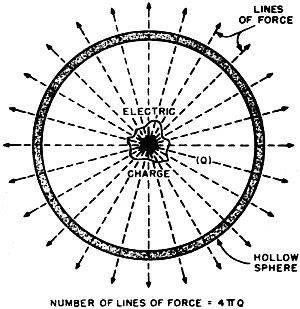
Fig. 4 - The number of lines of force leaving any electrical
charge is (by definition) equal to 4π x the charge.

Fig. 5 - Configuration of electric lines of force, (A) for
attraction and (B) repulsion.
The next phase that interested the scientists after they had formulated the ideas
of electric charge and electric force or intensity was to get the exact relationship
between the charge and the amount of electric field intensity due to this charge.
The problem was this: Suppose there was some charge inside a hollow sphere. How
is the number of lines of force or how is the electric intensity related to this
charge The answer is known as Gauss' Law and in words it states that the net outward
electric flux (or lines of force) from any charge in all directions is 4π
times the amount of charge Q. See Fig. 4. Thus there are two fundamental relationships
that hold in a region containing electric charge:
1. First is Coulomb's Law and this sets up the idea of electric charges and the
forces between them.
2. And second is Gauss' Law which gives the exact relationship between the force
set up by any charge and the amount of the charge itself.
It is to be noted that whenever lines of force are drawn they are always shown
with arrows (Figs. 2 and 5). These arrows are meant to indicate the direction in
which the electric force due to the charge act. The electric theory was first developed
by men who postulated that the lines of force should have arrows on them pointing
in the direction that a positive charge, if placed near any electric charge, whether
positive or negative, would go. This means that if a certain space were filled with
protons or positive charges, then all the lines of force would point away from these
positive charges since they would repel an exploring positive particle in this field.
On the other hand, negative charges would attract this exploring positive charge
and so the arrows on the lines of force connected with negative charges point toward
the charge itself. All this sometimes tends to be confusing and so it is better
to just think of these lines of force as an actual force which will attract oppositely
charged particles and repel like charges.
With this in mind, no confusion should result. These lines of force are continuous,
starting out from positive charges and ending up on negative charges. Should the
space in question contain only positive charges, then the lines of force due to
these charged particles will continue indefinitely out into space toward infinity,
and a force would everywhere be felt. This is theoretically true but in an actual
case the effect of its electric intensity would be confined to the immediate vicinity
since from Coulomb's Law it can be seen that force varies inversely as the square
of the distance. At a distance of say 8 centimeters from a charge the force would
be 1/16 of what it is at 2 centimeters from the same charge, so it is obvious that
no great distance is needed before the overall effect of the electric field is negligible.
A clear idea of the way these forces decrease with distance can be obtained from
Fig. 1.
Dynamic Electricity
Turning now from the static case, let us put an electric charge (for example,
an electron) into motion and see if any new facts are discovered. The easiest method
of accomplishing this end is to use a conductor, that is, a substance that contains
a large number of free electrons. Since the free electrons will experience a force
when any electric field is brought to bear on them, they will be forced to move
and the number that will flow past any point in this conductor will be determined
by the strength of the electric force that is causing them to move plus the ease
with which they can travel through this conductor. Does the last statement sound
familiar? It should, for although it is never stated this way, it the good old formula
E = IR which is Ohm's Law. Note that a steady electric field or electric force is
used here - a situation that is true for direct-current circuits.
Since the electron has a charge it will produce an electric field. But it has
been found on investigation that when put into motion the electron will likewise
give rise to a magnetic field. In 1819 the Danish physicist Oersted discovered that
current in a wire affected a compass that was held near this wire. Since compass
needles will only move under the influence of magnetic fields, Oersted concluded
that there must be a magnetic field about a wire carrying a current.
A little while later Ampere carried this one step further and showed that two
wires with currents in them exerted forces on each other. With the two wires separate
and distinct from each other it must have been the magnetic field that reacted.
It is from the above that the first ideas on the relationship between electric and
magnetic fields were brought into existence and slowly started the trend that ended
with Maxwell's formulation of the electromagnetic theory.
The type of magnetic field produced depends on the type of electric current that
is flowing in the wire. A steady flow of electrons will produce a magnetic field
that is likewise constant in value, while changing magnetic fields are the product
of changing electric currents.
This idea of electric currents giving rise to magnetic fields was proved time
and again and was accepted without question in the 19th century. However, in the
theories that Faraday and, a little later, Maxwell envisioned about electrodynamics,
there was more to the story than just the above. Must currents always be present
for magnetic fields to occur? - questioned Maxwell. Was it not possible to deal
only with a varying or changing electric field and derive magnetic effects from
this? Maxwell claimed that it was possible and so added this revision to the existing
electric field equations that were accepted at that time. He postulated two types
of currents; one was called conduction current and this was our ordinary flow of
electrons along any good conductor. The second type of current, due not to actual
moving electrons but rather changing electric fields, he called displacement currents.
Both, he said, gave rise to magnetic fields.
A classical example to illustrate the above is given with a fixed condenser in
a setup such as shown in Fig. 6. Closing the battery switch will cause current
to start flowing in the circuit. Since electrons do not flow across the space between
the plates, it might be said that the circuit is open at this point. However, since
the number of electric lines of force between the plates are changing, due to the
charging effect of the condenser, then, according to Maxwell, the circuit is now
no longer open at this point. Instead of electrons or conduction currents flowing
across this space, we now have a displacement current and the circuit is continuous.
It would even be possible to detect a magnetic field produced between the condenser
plates during that portion of the time when the condenser is charging up and the
electric field is varying in this region. The entire process ceases, of course,
when the condenser becomes charged.
The above was all that was needed to allow Maxwell to set up his basic equations.
From these he developed the idea that electromagnetic waves travel through space
at. a finite or measurable velocity which we know to be approximately 186,000 miles
per second.
Electric and Magnetic Fields
If the reader is a bit puzzled as to why Maxwell needed this added idea of changing
electric fields giving rise to magnetic fields, let him pause for a minute and stop
to consider that in the space between the transmitting antenna and the receiving
antenna there is no flow of electrons at all.
Posted April 18, 2023
(updated from original post
on 11/10/2014)
|


