|
|||||||||||||
 |
|||||||||||||
Practical Radar (part 5) |
|||||||||||||
After having begun my electronics career in the USAF as an airport surveillance radar technician, my interest is always piqued by articles on the subject. Like so many other types of electronics, radar is so common today that not many people think it is anything special - just another convenience that has been around for as long as they can recall - and indeed it likely has been since radar was first put into practical operation in the early 1940s. In 1945, the last year of World War II, Radio News magazine ran a multi-month series on radar system theory of operation and design. When I look at the detailed block diagram, it brings back memories of the MPN-14 search and precision approach radar systems that I worked on. In tech school at Keesler AFB, Mississippi, we spent nine months for 7 hours per day, five days per week with piles of schematics learning stage by stage how the entire system worked. The primary radar systems, VHF, and UHF navigation radios were vacuum tube based, while the Identification Friend or Foe (IFF), video mapper, and a handful of other secondary systems actually had those newfangled transistors in them. RF, IF, and video processing was all done via analog circuitry. The early radar engineers were an ingenious bunch. Here are the installments available: Part 1 - June 1945, Part 2 - July 1954, Part 5 - October 1945. Practical Radar Part 5: The design of radar receivers capable of detecting weak echo signals. Conventional u.h.f. tubes, circuits, and design techniques are used throughout.
Illustrated by Julian Krupa
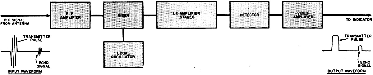
Fig. 1 - Basic block diagram of a radar set. A constant barrage of r.f. pulses from a radar set scans the air and land and sea, searching for targets in light or darkness, in any kind of weather. The pulses travel at the speed of light until they strike a target, when the r.f. energy is reflected or reradiated at equal speed in all directions from the surface of the target. Some of this reflected energy returns to the radar set in the form of echoes which are picked up by the radar receiving antenna. The receiver takes every weak echo from the antenna, amplifies it, detects the echo envelope, and then feeds the rectified signal to the indicator unit of the radar set. Once the echo signals are received from targets, determination of the ranges and directions of the targets are based on the facts that radio-frequency energy travels at a constant velocity (about 186,000 miles-per-second) and that the antenna set of a radar set is movable and highly directional. The range or distance to a target can be found by multiplying the velocity by one-half the time a single pulse requires to complete a round-trip cycle, known as a radar cycle. This time is measured electronically by the cathode-ray oscilloscope and immediately translated into terms of distance - in yards or miles. The physical position of the antenna system then gives us two angular measurements, the azimuth or bearing, and the elevation angle of the target. Knowing the range or distance, azimuth, and angle of elevation, we can locate accurately the position of any object in space or on land or water. The reception and detection of echoes from distant targets is an important job in the overall function of a complete radar set (Fig. 1). Because reflections from any target are scattered at random in all directions, the few echoes that return to the radar set are very weak. Yet these signals must be accepted by the receiver and amplified sufficiently so they can be observed as visual signals on the time base of a cathode-ray oscilloscope. This ability of the receiver to detect and amplify extremely weak echo signals is a measure of the effectiveness of the radar equipment; the weaker the acceptable echo signal, the greater the workable range of the radar set. Radar receivers employing, for the most part, conventional types of u.h.f. tubes and circuits require a fairly wide bandwidth input, at the same operating frequency as the radar transmitter. Except in this one respect, the radar receiver needn't differ greatly from other u.h.f. receivers. Therefore, much of the published and known theory of u.h.f. receiver operation is applicable to radar receivers. The Superheterodyne A radar receiver must supply considerable amplification, with inherent stability and extreme sensitivity. For this purpose a superheterodyne circuit logically offers itself. Special types of high-frequency tubes with low interelectrode capacitances are used in the r.f., local oscillator, and i.f. stages. And a large number of i.f. amplification stages may be expected in a radar receiver. These and other u.h.f. refinements give stability of operation at ultra-high frequencies, as well as a high degree of sensitivity. Even when the receiver employs as many as six or eight stages of i.f. amplification, there is considerable stabilization. The block diagram of a basic superheterodyne receiver suitable for radar is shown in Fig 2. It functions much in the conventional manner, with some important exceptions. The input to the receiver is broadly tuned with provisions for changing the input bandwidth; the intermediate frequency is measured in megacycles and the output of the receiver is a video signal containing a wide range of component frequencies. A number of other circuit conditions must be considered in addition, if the radar receiver operates at ultra-high frequencies. High amplification by any one r.f. stage is seldom possible and there are considerable losses in the process of conversion to an intermediate frequency. The shortness of interconnecting leads becomes important. Interlocking of amplifier and local oscillator tuning becomes more difficult to avoid. All r.f. and i.f. circuit elements must be well shielded. Tuned sections of transmission lines are often used as "tank" circuits, and special types of u.h.f. tubes must be used in the r.f. local oscillator, and i.f. stages of the receiver. In general, as the frequency of operation is increased, the physical structure and electrical design of radar superheterodyne circuits becomes more radically altered. All of this is necessary to preserve the shape of the reflected echoes, while they are being detected and amplified. It's a big job for the radar receiver. Often the simple diagram (Fig. 2) may become quite complicated, as shown in Fig. 4, where as many as 20 or 25 separate and distinct stages compose the complete receiver. But regardless of the total number of stages in a radar superheterodyne, the receiver can be conveniently divided into five principal parts; the radio-frequency amplifier stages, the mixer or frequency conversion stage, the i.f. amplifier stages, the (second) detector stage, and the video amplifier stages.
Fig. 2 - Basic block diagram of radar superheterodyne receiver. Problems of Noise Like other u.h.f. receivers, the radar receiver is faced with the eternal problem of noise disturbances generated within the circuits of the receiver itself. If it were not for this problem, any number of amplification stages could be used to increase the amplitude of the echo signal, no matter how weak, by any desired amount. These noise disturbances actually are random, minute voltage variations due to any of several circuit conditions - usually associated with radio-frequency amplifier stages of the receiver. The effect of these noise voltages depends not so much upon their individual amplitudes, but upon the power relation between the echo signal and the collective noise. If the amplitude of the noise voltages is not less than the amplitude of the echo signal, the echo cannot be recognized at the out-put of the receiver. For this reason, the noise voltages must be kept as low as possible; i.e., the signal-to-noise ratio must be kept high. The lower the noise level, the weaker the acceptable echoes - and the greater will be the working distance of the radar set. Thus, internal noise in the early stages of the receiver directly affects the useful range of the equipment.
Fig. 3 - Basic block diagram of superregenerative receiver. There are three different kinds of noise disturbances in the r.f. section of a receiver; noise due to thermal agitation, noise due to shot effect, and hum or induced noises. Thermal agitation - the random motion of electrons in a conductor - is caused primarily by either high conductor resistance, or high operating temperature. Shot effect - the irregular emission of electrons by the cathode of the r.f. amplifier tubes - is caused by low filament operating temperatures, resulting in a low space charge within the tube. Stray electrostatic or electromagnetic fields often induce hum and other extraneous noises into a u.h.f, circuit. This is a form of modulation and generally exists when units of the r.f. stages are not properly shielded. While it has not been possible to eliminate the noise disturbances caused by these three effects, most of them have been minimized by improved u.h.f. design and the use of special tubes. Atmospheric "noise," or static, is another contributing factor to the sensitivity of the radar superheterodyne. A fairly wide input bandwidth would be required by most receivers, since the video output of the receiver must contain a wide range of frequencies, i.e., be rich in harmonics. for faithful reproduction of the echo pulse. This wide bandwidth admits a greater amount of spurious external "noise" and atmospherics, which usually must be contended with unless some form of variable input bandwidth is used in the first r.f. stage of the receiver. Considerable noise may be minimized or even eliminated by dividing the superheterodyne receiver physically so that the r.f, stages and mixer are located near the antenna system, and the i.f. and video stages are located elsewhere, near the main components of the radar equipment. Parts of the receiver may often be distributed throughout the radar set so that their physical identity becomes lost. However, for purposes of our discussion we will assume the receiver to be a complete component, consisting of the r.f. amplifier, frequency conversion, i.f. amplifier, and video amplifier stages. Glossary of Radar Terms Antenna array - A symmetrical arrangement of dipoles with directional characteristics. Antenna reflector - See reflector. Antenna switch - See T-R switch. Azimuth - Bearing or angular direction relative to true north. Beam width - The width in azimuth of the pulsed r.f. energy beam. Bearing - See Azimuth. Blocking oscillator - Tuned-grid, tuned plate r.f. oscillator in which the grid circuit controls the pulse duration. Carrier frequency - The ultra-high frequency at which a radar transmitter operates. Cathode follower - Distortionless, impedance-matching, isolating stage. Charged line - A pulse-shaping network which reflects a steep-sided rectangular pulse of a duration determined by the electrical constants of the line. Clamping circuit - A circuit which holds either the positive or negative amplitude extreme of a wave form to a given reference level of voltage. Crystal mixer - Mixing two frequencies by using the non-linear characteristics of a crystal. Cut-off limiting - Limiting action of an amplifier when operated beyond the point of plate current cut-off. D.C. restorer - See clamping circuit. Delay circuit-Network or circuit which introduces a time or phase delay of a wave form. Differentiator circuit - A short time constant (RC) circuit and amplifier which produces an output voltage with an amplitude proportional to the rate of change of the input voltage. A circuit used to sharpen a wave form sometimes called a peaking circuit. Dipole - A half-wave, center-fed radiating element. Duty cycle - The fraction of a, complete radar cycle during which energy is transmitted. Echo - That part of the r.f. pulse reflected back to the radar set by a target. Electronic timer - The component of a radar set that originates the pulse recurrence frequency, and synchronizes the operation of other components with the radiation of r.f. pulses by the transmitter. Elevation angle - The angle of the target with respect to the radar set and the horizontal plane of the earth. Envelope - The general outline of a wave form. Gate - A rectangular wave used to switch a circuit on or off electronically during certain portions of the radar operating cycle. Grass - Static or noise appearing as intermittent, minute interruptions of the oscilloscope time base. Ground return - That part of the r.f. pulse reflected by the ground surrounding the radar set. Indicator - Any of several types of cathode ray oscilloscopes. Indicator gate - See Gate. Isolating circuit - A stage which passes signals in only one direction through a circuit. Klystron - A velocity modulated tube used to produce low-power u.h.f. oscillations. Lighthouse tube - A high-frequency triode of special design used to produce u.h.f. oscillations of medium power. Limiter - A circuit which limits, clips, or removes either (or both) the positive or negative extremities of a wave form. Listening period - The time during which a radar transmitter is quiescent or not radiating energy. Magnetron - A high-frequency magnetic-field diode of special design used to produce u.h.f. oscillations of very high power. Main pulse - See Transmitter pulse. Master oscillator - A source pf timing oscillations which control or affect all other radar circuits. Microsecond - One millionth of a second. Modulator - A circuit which directly controls or triggers the radar transmitter. Multivibrator - A relaxation oscillator which oscillates of its own. accord (a free-running multivibrator), or which oscillates only when triggered by an external voltage. Overdriven amplifier - Amplifier circuit in which the combination of cut-off limiting and saturation limiting of a sine wave produce a rectangular voltage wave. Peaking circuit - A differentiator circuit used to sharpen a wave form. Peak power - The maximum output power of an r.f. pulse at the transmitter. Presentation - The form in which radar echoes appear visually on an oscilloscope. Pulse - A sudden change of voltage (or current) of brief duration. Pulse duration - The time duration of a pulse. Pulse generator - See Electronic timer. Pulse rate - See Pulse recurrence frequency. Pulse recurrence frequency or p.r.f. - The timing rate of radar pulses, originating in the electronic timer. Pulse recurrence time - The reciprocal of pulse recurrence frequency. Pulse width - See pulse duration. Quiescent period - See Listening period. R.F. oscillator - Output stage of the radar transmitter in which u.h.f. oscillations are generated. Range - The direct-line distance between a radar set and a target. Receiver - The component of a radar set which receives, detects, and amplifies echoes reflected from targets. Receiver gate - See Gate. Recurrence rate - See Pulse recurrence frequency. Reflector - A metallic object or surface behind a radiating dipole to reinforce radia-tion in a desired direction. Reflex Klystron - See Klystron. Repetition rate - See Pulse recurrence frequency. Ring oscillator - Any number of pairs of high-frequency triodes operated as an r.f. oscillator in a tuned-grid tuned-plate circuit. Rotary spark gap - A pulse-protruding device in which circularly arranged electrodes are rotated past a fixed electrode producing periodic high-voltage arc discharges. Saturation limiting - Limiting action of an amplifier when operated beyond the point where grid current flows. Scanning - The direction of pulsed r.f. energy over or across a given region or area. Sea return - That part of the r.f. pulse reflected by water surrounding a sea-borne radar set. Spark gap - An arrangement of two fixed electrodes between which a high-voltage arc discharge takes place. Squaring amplifier - See Overdriven amplifier. Squegging oscillator - An extreme form of grid blocking in an r.f. tuned-grid tuned-plate circuit. Synchronism - The relationship between two or more periodic or recurrent wave forms, when the phase difference between them is zero. Synchronizer - See Electronic timer. T-R switch - A device which switches a radar antenna between the radar transmitter and receiver, preventing transmitted energy from reaching and damaging the receiver. Tail - Attenuated decay of an r.f. pulse. Target - Any object which produces a radar echo. Time base - The trace produced on the screen of a cathode ray tube by horizontal deflection of the electron beam. Time constant - An indication of the speed with which a circuit can be charged or discharged. Timer - See Electronic timer. Transmitter pulse - Burst of r.f. energy radiated by the radar transmitter. The pulse appears as a strong signal at the left end of the oscilloscope time base. Unidirectional - In one direction only. Video amplifier - A circuit amplifying a very wide range of frequencies which includes and exceeds the audio range. Wave guide - A hollow pipe or tube, having a circular or rectangular cross-section, used to transmit r.f. energy. R.F. Amplification Probably most radar superheterodyne receivers use one or more stages of r.f. amplification, but at extremely high frequencies of operation this may be difficult. However, we can assume that at least one stage of r.f. amplification is generally used - sometimes two or three stages - providing a considerable degree of pre-selection. Because of noise disturbances, screen grid tubes are impracticable for r.f. amplification in radar superheterodynes. Inductive reactance of the cathode leads causes degeneration in the circuits associated with such tubes. Grounded-grid triodes offer advantages as r.f. amplifiers at the lower frequencies of radar operation. If the input signal is applied to the cathode, the plate-to-grid capacitance of the tube then acts only as a plate load, instead of the conventional feedback circuit. This absence of plate-to-grid capacitance is due to the shielding action of the grounded grid. At higher frequencies the Lighthouse tube has found considerable use as an efficient r.f. amplifier. But in the extremely high ranges. r.f. amplifier stages are seldom used in superheterodynes. All of the u.h.f. circuit techniques discussed earlier in this series on "Practical Radar" can be applied to this stage of the receiver. Every piece of connecting wire, no matter how short, acts as some portion of a transmission line. Lumped inductance and capacitance are of far less importance than distributed inductance and capacitance, and coaxial cables or wave guides are used to transfer r.f. energy over any appreciable distance in the set. Resonant circuits of the r.f. stages are of the fixed tuned type; that is, the stages are adjusted to a given frequency of operation, depending upon the carrier frequency of the radar transmitter. Tuning can be accomplished by variable condensers. R.f. chokes used in the plate and filament leads of the r.f. amplifier tubes prevent leakage of the signal into the power supply. Because of the high operating frequencies involved, low values of inductance are required. The chokes may be formed from the interconnecting leads which supply voltages to the different tube elements, a few turns being sufficient for this purpose. Every portion of the r.f. amplifier stage must be well shielded, and the complete stage also shielded from the rest of the superheterodyne. These, and many other "trick" u.h.f. techniques, could be employed in radar receivers, in an effort to supply as much undistorted r.f. amplification as possible to the echo signal before it is passed to the frequency conversion stage of the radar superheterodyne. Frequency Conversion Mixing or frequency conversion could be accomplished in a radar receiver by means of a separate local oscillator in a somewhat conventional circuit. However, it should be noted that the output of this mixing stage, the intermediate frequency, needs to be considerably higher than in the usual u.h.f. superheterodynes. At the lower operating frequencies of the r.f. spectrum, any of several types of high-frequency tubes can be used as the "mixer" with a stable local oscillator supplying the mixing frequency. Link coupling between the mixer and local oscillator, and between the mixer and the first i.f. amplifier stage, would obtain the optimum degree of energy transfer between these stages. This method of coupling prevents interaction between the circuits due to heavy loading, such as would occur with other types of coupling. Radio-frequency chokes would be as efficient in the power leads to the mixer stage as in the r.f. amplifier stages previously described. The local oscillator might use any type of stable oscillatory circuit, and the tuning can be adjusted over a slight range of frequencies. The local-oscillator frequency may be slightly higher or lower than the r.f. signal, by an amount which represents the "difference" or intermediate frequency. Frequency conversion at the higher operating frequencies of the u.h.f. spectrum becomes much more difficult and requires something of a new philosophy of "mixing." One type of local oscillator capable of generating a high frequency for mixing purposes is known as the Klystron tube [Sperry] functioning in a very simple circuit. Also known as a reflex Klystron, this tube can generate radio waves of very short length. The Klystron tube consists essentially of a cathode, a control grid, a repeller electrode, and a resonant cavity. The tube operates on the velocity-modulation principle, in which the transit time of electrons between the resonator and the repeller is utilized. Oscillations take place within the resonant cavity when properly phased electrons pass between the resonator grids. This phasing can be affected by the accelerating voltage of the electrons, the voltage of the reflector, or the resonant frequency of the cavity. Thus, anyone of these interrelated variables can be used to tune and adjust the Klystron for operation at any desired local-oscillator frequency. I.F. Amplification The large amount of gain required in a radar receiver is obtained by considerable amplification of the intermediate frequency, thus requiring a large number of i.f. amplifier stages. The intermediate frequency may be quite high, while some radar receivers function with a considerably lower i.f. signal. An important factor governing the choice of intermediate frequency is the bandwidth of the circuits. The width of the frequency channel passed by the i.f. amplifier is determined by the spectrum range of the returning echo signal. Since reception of the signal is of the double-sideband variety, this region allows for sufficient uniform amplification of all video frequencies. The frequency bandwidth must be fairly wide to pass all of the component frequencies contained in the received r.f. signal. To fix the bandwidth within acceptable limits, "damping" resistors could be used in the i.f. circuits. The sensitivity as well as the selectivity of the entire set will suffer if the bandwidth of the i.f. amplifier is too wide. Losses in the i.f. amplifier stages can be made almost negligible by using very close coupling between the primary and secondary windings of i.f. transformers. In order to vary this coupling, the physical location of the primary winding can be changed with respect to the secondary winding. This coupling adjustment is particularly critical in the first stage of i.f. amplification. The first i.f. stage should be operated with the lowest possible noise level, in an effort to obtain as high a signal-to-noise ratio as possible. Following stages of i.f. amplification may be primarily straight i.f. amplifiers, operating under similar but not so exacting conditions as the first stages. All i.f. stages are double-tuned. Since gain values as high as 100 db. can be expected from the combined stages of i.f. amplification, tendencies toward regeneration must be carefully controlled by filters and proper shielding. Lead shielding and filters can also prevent the receiver from being oversensitive to strong external r.f. and a.f. fields. Although the radar receiver is protected by the T-R switch (Fig. 1) from transmitter power surges, a small signal is permitted to "leak through" the receiver in order to register as a strong pulse - or "transmitter" pulse - at the beginning of the time base of the indicator oscilloscope. This r.f. signal directly from the radar transmitter may have a blocking effect each time the pulse passes through the receiver. To counteract this possibility, a gate pulse could be applied to the second i.f. amplifier stage. The gate pulse consists of a rectangular voltage wave controlled by the electronic timer. The wave would be applied to one or more of the i.f. stages and could either bias the tube(s) to cut-off, or completely remove the plate voltage during the time the transmitter is pulsing. This, in effect, is a protective device to prevent the i.f. stages from overloading due to the extremely powerful input pulses from the transmitter. After the desired degree of amplification has been obtained by the i.f. stages of the radar receiver, the signal is detected - probably by means of a conventional diode - and the rectified output is then applied to the video stages of amplification.
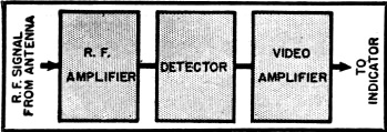
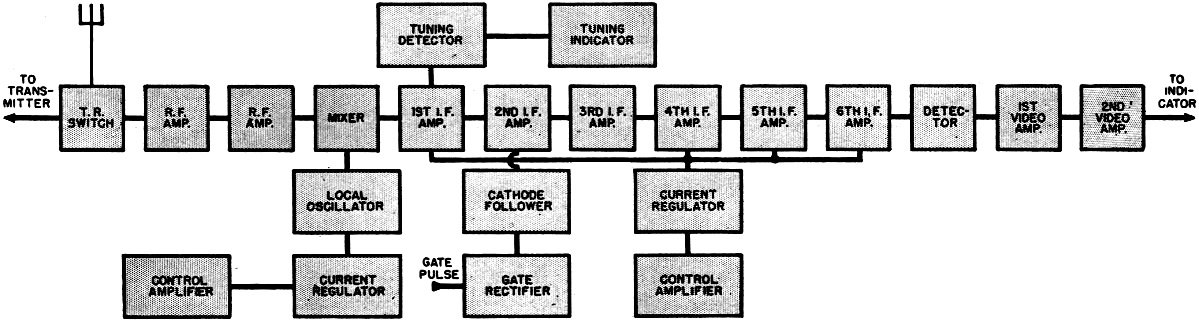
Fig. 4 - Detailed block diagram of radar superheterodyne receiver. Video Amplification An energizing voltage of from 50 to 200 volts peak with a bandwidth of about three megacycles is required by most cathode-ray tube circuits. It is the purpose of the video stages of amplification to supply this wide range of frequencies at the desired voltage amplitudes. Video-frequency amplifiers are usually resistance-coupled with a characteristically almost-flat gain response over the entire range of frequency operation, about three megacycles. Video-frequency amplifiers have been developed which supply from 30 db. to 50 db. of gain per stage with bandwidths as great as two megacycles. Use of the same circuits for bandwidths of about three megacycles, lowers the amount of stage gain to about 25-35 db. Some means of limiting the amplitude of the video output may be provided, to prevent defocusing of the cathode-ray tube due to strong signals. The output signal from the video amplifier is usually a negative-going pulse, applied to the grid of the cathode-ray tube. A positive-going pulse would be applied to the cathode of the indicator tube. The type of cathode ray oscilloscope used by the radar set would not normally influence the nature of the output from the video amplifier stage or stages. Superregenerative Receiver Another type of receiver offering radar possibilities is the superregenerative receiver (Fig. 3). A superregenerative oscillator forms the basis of this type of receiver. Superregeneration takes place when oscillations are started and stopped at an r.f. rate which is low in comparison with the frequency of the generated voltage. This is accomplished by means of a quench oscillator. The incoming r.f. signal from the antenna is applied to the grid of the superregenerative stage. Since the tube is operated in a highly regenerative state, there will be very high amplification of the signal during periods of oscillation. Because of the limiting action of the circuit, the video output doesn't depend on the strength of the input r.f. signal. Although the sensitivity of a superregenerative receiver is very high, its lack of stability, and other disadvantages, prevents wide use in radar applications. (To be continued)
Posted May 2, 2022 |
|||||||||||||
 |
|||||||||||||
|
|||||||||||||

 By Jordan McQuay

|
||||||||||||||||||||||||||||||||||||


