|
|||||||||||||
 |
|||||||||||||
The Unidirectional Dipole Loop Antenna
|
|||||||||||||
This article from a 1959 issue of Radio-Electronics magazine details a simple, effective method to convert a standard dipole antenna into a unidirectional, broadband performer by bending it into a circular loop and terminating the ends with a non-inductive resistor. By utilizing a cross-shaped support frame with TV standoff insulators, a builder can easily construct this antenna for the 6-meter band or higher. The design is noted for its impressive front-to-back ratio and surprising operational versatility across a wide frequency range, even maintaining performance when improperly sized. Offering increased gain at harmonic modes and requiring only basic materials like aluminum wire and a wooden mast, this unidirectional loop provides a practical, high-performance alternative for radio enthusiasts seeking straightforward directional reception and transmission. The Unidirectional Dipole Loop Antenna
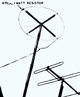
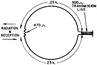
The Unidirectional Dipole Antenna By Leonard E. Geisler Anyone who has peeked inside one of the many radio handbooks is familiar with the figure-8 radiation pattern of the dipole (or doublet) antenna. However, most readers probably are not aware that you can make a highly directional, broad-band antenna from the simple dipole without resorting to additional elements -other than one resistor, some TV standoff insulators, spars and a little labor. By simply bending the conventional dipole into a perfect circle and joining the two ends opposite the feed point with a noninductive resistor, the antenna becomes unidirectional (Fig. 1). Radiation and reception take place only on one side of the loop - the one terminated by the resistor.
Fig 1 - Basic unidirectional dipole loop antenna.
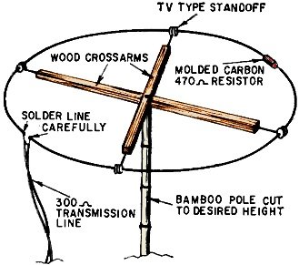
Fig. 2 - A practical unidirectional dipole loop antenna. To build such a dipole, say for 6-meter ham-band operation first find the length of a half-wave (0.5λ) radiator for the low side of the band. This would be approximately 110 inches long. Since the antenna is bent into a circle with a 110-inch circumference, we insert this value in the formula: C / 3.1415 = D where C is the circumference, 3.14 is pi (approximately) and D diameter or, in this case, length of the cross-piece with the installed length of TV standoff insulators subtracted. Assembly details are shown in Fig. 2. After the cross-shaped support is assembled, proceed to thread two 55-inch lengths of radiator through the eyes of the TV standoffs. Unless quite stiff, large-diameter wire or tubing is used, be careful and preserve the circular shape. Use aluminum clothes line, No. 10 enameled copper wire or ¼-inch copper tubing for optimum results. Fasten the completed loop assembly to a bamboo or wood mast and bring the 300-ohm ribbon line down as nearly at right angles to the antenna as possible. Avoid placing undue strain on the antenna proper. Aim the side opposite the feeders in the direction you wish to receive from (or transmit to) and you're on the air! Simple, isn't it? Of course, this antenna is cut for the low edge of the 6-meter band. How ever, its excellent front-to-back ratio (5 to 1 approximately) will hold good far above that frequency. By a minor error, we designed and constructed a similar 108-mc antenna - learning about 3 weeks later that we had cut it for just half that frequency - and during the entire 3-week period had such phenomenal reception that we told all our friends about it. Only after the error in our arithmetic was pointed out did we realize just how broad-band the antenna was! Because of this error, we decided to test the antenna carefully. We found that it would actually operate with little or no change in front-to-back ratio until we reached the third-harmonic mode of operation, where the antenna's gain actually increased while beam angle was reduced only by a small amount. Our conclusion was that the unidirectional dipole was the job we needed. If you wish, several similar units may be stacked vertically, 0.5λ apart, along the same mast and fed in parallel. This improves the front-to-back ratio and beam angle, along with a proportional increase in gain. Frequency sensitivity changes very little. The value of the terminating resistors has to be increased in proportion to the number of elements used for proper transmission-line termination. By spacing two of these antenna elements one or more wavelengths apart - vertically - and connecting them to a common feeder via a transmission-line hybrid, excellent space diversity reception and transmission may be enjoyed. By using this system we have found that gains of the order of 10 db or more are common over long-haul dx routes. If you use the unidirectional dipole with a transmitter, the terminating resistors must have a wattage rating high enough to prevent burnout. A good safe value is 10% more than the input power to your final amplifier. (A portion of the material presented here was obtained from "Technical Notebook" in Wireless World, October, 1957.) |
|||||||||||||
 |
|||||||||||||
|
|||||||||||||


|
||||||||||||||||||||||||||||||||||||


