|
|||||||||||||
 |
|||||||||||||
Space Relay Station
|
|||||||||||||
The "Space Race" was in full swing when this "Space Relay Station" article appeared in a 1959 issue of Radio-Electronics magazine. The Russkies launched Sputnik into Earth orbit on October 4, 1957. The U.S, to its shame, didn't orbit a satellite until January 31 of the next year (Explorer 1). In December 1958, Project SCORE marked the first successful demonstration of space-based communications using an orbiting relay station aboard an Atlas missile. This military-industry collaboration proved the feasibility of global communication via satellite, transmitting both voice recordings and multi-channel teletype signals. The 35-pound communications package operated in three modes: storing messages on magnetic tape for delayed broadcast, instantly relaying signals, or broadcasting pre-recorded messages. The project demonstrated how space relays could overcome terrestrial propagation limits, enable selective transmission timing, and potentially solve spectrum congestion - heralding a new era in global communications technology that would eventually evolve into modern satellite systems. This passage from the article suggests that stable geostationary orbits (~22,236 miles above MSL) had not yet been deemed achievable: "When required, future satellites can be controlled to hover as fixed radio relay stations. Four or five of these at strategic locations in space will assure communications with any part of the earth, no matter how remote or inaccessible." Space Relay Station
A new era in electronic communications opens with this first out-of-the-world rebroadcaster. By Jordan McQuay Successful orbiting late in December, 1958, of an Atlas missile-satellite carrying a communications relay station was more than a step forward in space exploration - it was the first advance in the science and techniques of global communication via a relay station in outer space. Not merely a quasi-propaganda stunt of broadcasting a taped message by the President, it was a carefully planned and singularly successful experiment by military and industry engineers and technicians. It marked the beginning of world-wide communications using satellites in space as relay stations. For the first time, voice and teletypewriter messages were accepted by a satellite in space, carried thousands of miles and, on command, broadcast directly to ground stations. For the first time, signals from earth were received by an orbiting relay station and re-broadcast over a greater range than possible with conventional ground-based facilities. For the first time, both the feasibility and importance of space relay communications were proven dramatically and conclusively.
Fig. 1 - Communications relay station: project SCORE.
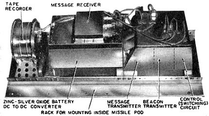
Fig. 2 - Electronic components of satellite: In hand, all-transistor FM receiver. Behind it, control or switching circuit. Large unit (center), 8-watt FM message transmitter. Left, power converter. Round unit (foreground), beacon transmitter.
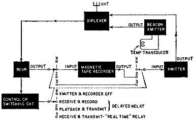
Fig. 3 - Block diagram of space relay station.
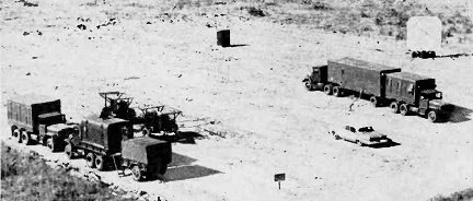
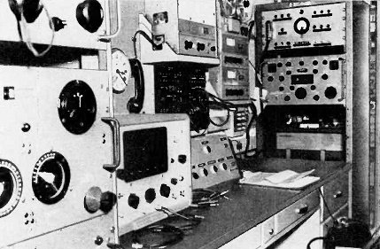
Fig. 4 - Typical ground station of the system. U.S. Army photo
Fig. 5 - Helix type antenna array of ground station. U.S. Army photo Though the gigantic size of the Atlas missile that became an earth satellite was impressive, engineers and technicians were even more concerned with the scientific significance and historic importance of the first space relay station. Known as Project SCORE - Signal Communications by Orbiting Relay Equipment - the space relay station was an Army- designed communications "package" (Fig. 1) carried aboard an Air Force Atlas missile-satellite. During the 13-day life of Project SCORE, a variety of technical tests - using both a voice signal and as many as seven teletypewriter signals, singly and in groups - were conducted between the orbiting space station and ground stations of the Army Signal Corps. First in Space The Atlas missile which placed the relay station in orbit was technically a 1½-stage rocket. In addition to its single engine, it used ground-fired booster engines which dropped off when the 4½-ton missile gained sufficient height and momentum. Equipped with an elaborate internal guidance system, the Atlas followed a calculated path, broke through the earth's lower atmosphere and went into orbit at a height varying between 120 miles at perigee and 620 miles at apogee. Once in its elliptical orbit, the missile-satellite traveled at about 17,000 miles an hour, making vast loops around the earth once every 100 minutes. After a dozen orbits, the space relay station aboard the satellite was triggered by an Army ground station and, for the first time in history, man's voice was broadcast to earth from outer space. It was a brief message by the President, previously fed to the relay station and stored for that broadcast. Thereafter, the same message was transmitted from the ground to the orbiting relay station, where it was either rebroadcast immediately or stored by a magnetic tape recorder and rebroadcast later "on cue" from the ground. Subsequently, single- and multi-channel teletypewriter signals replaced the voice message. Using a bandwidth of 300 to 5,000 cycles, the space relay station continued to operate as either a "real-time" relay or a delayed repeater. All signals broadcast by the orbiting relay station were transmitted on a frequency of 132 mc. The FM signals could be heard by anyone with suitable receiving equipment. Control of the space station from the ground, however, was not a public matter. This control-loading, switching and triggering - was limited to any of four ground stations of the Signal Corps strategically located at sites in California, Arizona, Texas and Georgia. To prevent jamming or unauthorized use of the space relay station, the ground stations used an unpublicized frequency for transmitting orders and messages to it. In addition, a specially coded signal switched circuits within the relay station to establish any of three modes of operation: 1. Receive signals from the ground, and record them on magnetic tape; 2. Broadcast previously stored signals to earth; 3. Receive signals from the ground and rebroadcast them immediately. With various types and volumes of traffic, testing each of these three modes of operation continued until the space station's only source of power - a battery of zinc-silver oxide cells - was exhausted. By that time, all scheduled tests of the entire system had been completed successfully.' The Space Station A complete space relay station is contained entirely within part of one of the two pods or elongated "fins" on either side of the main body of the Atlas. The main body, containing mostly fuel, is 10 feet in diameter and about 80 feet long. The entire payload is divided between and enclosed within the two flanking pods or fins. Most important part of this payload is the space relay station - a single "package" about 25 x 9 x 10 inches (Fig. 1), weighing about 35 pounds. Controlled remotely and equipped with its own power supply, it is electronically independent of other parts of the Atlas. (See Fig. 3.) The complete space relay station includes an FM message transmitter, an FM message receiver, a control or switching circuit, a magnetic tape recorder, a beacon or tracking transmitter, a dc-to-dc power converter and a zinc-silver oxide battery. Communications components are shown in Fig. 2. The outputs of the two transmitters and the input of the receiver are connected by a diplexer to a single slot type antenna in the housing of the pod or "fin."
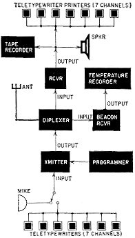
Fig. 6 - Block diagram of typical ground station associated with space relay system. The FM message transmitter operates nominally at a crystal-controlled frequency of 132 mc. With a complement of nine tubes, the transmitter delivers 8 watts of output power into an impedance of 50 ohms. Bandwidth limits are 300 to 5,000 cycles. Required input operating power is 39 watts at dc voltages of -6, 135 and 270. The FM message receiver operates at nominal frequency of 150 mc, in direct contact with the transmitter of each ground station. Receiver sensitivity is 2 microvolts. Its output level is 0.5 volt across 1,000 ohms - for a fully deviated signal. The receiver is an all-transistor unit and requires only 25 mw of input power. The control or switching circuit is essentially an arrangement of selective filters that provide the three basic modes of operation. It is fully transistorized. When activated by appropriate command signals from a ground station, it provides any of four types of switching (Fig. 3). The magnetic tape recorder is conventional, with a 4-minute storage capacity for audio signals or analog data within bandwidth limitations. This storage capacity can accommodate seven 60-word-per-minute teletypewriter channels, for a total of about 1,680 telegraphic words. A second transmitter - known as a beacon or tracking transmitter - transmits a telemetered signal at a nominal OUTPUT XMITTER frequency of 108 mc and is crystal-controlled. It has an output power of about 20 milliwatts into an impedance of 50 ohms. An all-transistor unit, it requires an input operating power of 250 mw at dc voltages of -6 and 18. The steady signal output of this transmitter permits tracking the satellite by Minitrack and other ground monitoring stations - including amateurs with appropriate converters for their receivers. The output signal is also telemetered with temperature data from within the pod-enclosed space relay station. Temperature variations between 0° and 200 °C are recorded directly and broadcast by this transmitter independently of other operations of the space station. Primary power source for the station is a battery of zinc-silver oxide cells which provides dc voltages of -6, -7.5, -12 and -18. Although these have a limited operating capacity of about 950 watt/hours, they were selected because of the anticipated short life of the missile-satellite and the relatively short duration of the planned communications experiment. Supplying higher voltages, an all- transistor dc-to-dc converter delivers 135 and 270 volts dc.
Fig. 7 - Control desk of ground station. Left: remote -control equipment for orienting helix type antenna array. Right: FM message receivers. RCA developed most of the communications equipment of the space relay station in coordination with the US Army Signal Research and Development Laboratory at Fort Monmouth, N. J. Relay of Messages The FM message receiver in the space relay station operates continuously. But the FM message transmitter and the magnetic tape recorder are switched on and off, as required, by the control or switching circuit. This circuit is actuated by a special coded signal, transmitted to the satellite by any one of the four Army ground stations. Upon reception, this special signal causes a multiple switch to move to one of four positions (Fig. 3) to select any of three modes of operation. In position 1, the magnetic tape recorder is turned on and its input connected directly to the FM message receiver's output. In this mode, signals received from the ground are recorded and stored on magnetic tape. With a continuous capacity of 4 minutes, the signals may be stored indefinitely for later use. Also, when directed by a ground station, all or part of a previously recorded message may be wiped clean from the tape in preparation for a new recording. After position 1, the control circuit moves the switch to position X. In this position, the output of the FM message receiver is disconnected from the recorder's input, and the recorder is turned off. In position 2, the recorder's output is connected to the input of the FM message transmitter, and the tape recorder and FM transmitter are turned on. Messages stored on the magnetic tape are fed to and broadcast by the FM transmitter. After position 2, the switch moves to position X, which disconnects the tape recorder and the transmitter, and turns off both. In position 3, the FM message receiver output is connected directly to the input of the FM message transmitter, and the transmitter is turned on for instantaneous relay of all signals. All signals received from a ground station are rebroadcast immediately by the FM message transmitter of the space station. After position 3, the control circuit moves the switch to position X, which disconnects the transmitter; but not the receiver, which operates continuously. The sequence of positions 1 to X to 2 allows the space station to function as a delayed repeater or "courier" of messages. Between positions 1 and 2, there is usually a period of inactivity - a few minutes, a few hours or even longer. This permits a high degree of selectivity of transmission by withholding signal transmissions until the satellite is over or near the intended recipient. In position 3, the space station functions as a "real-time" or instantaneous repeater. This permits the station to rebroadcast signals over greater ranges than possible for a ground station depending on conventional means of propagation of radio waves. With a space station sufficiently high in the sky, line-of-sight transmission is possible to most of the facing globe - nearly one-half the world. With several stations strategically placed in space, it would be possible to broadcast signals to the entire world. The Ground Stations Controlling the various operating modes of a space relay station and thereby functioning as key elements of the complete communications system are the several ground stations. During the experimental tests, four mobile ground stations were operated by the Army Signal Corps: at Prado Dam near Los Angeles, Calif.; at Fort Huachuca, Ariz.; at Fort Sam Houston, Tex., and at Fort Stewart, Ga. All are similarly equipped. Each ground station is housed in five trucks (Fig. 4) , which collectively contain all communications, recording, control and power equipment. The antenna array is a separate unit (Fig. 5). See the block diagram ( Fig. 6). A single helix type antenna array is used for transmitting control signals and messages, and for receiving messages and beacon or tracking signals from the orbiting space station. Most of the other equipment, essentially conventional, is provided largely by RCA and other industrial firms. A 1- kilowatt transmitter is used for sending messages and control signals from the ground station. Specially coded control signals are fed from a programmer. For messages, either a voice signal or from one to seven teletypewriter signals are used to modulate the FM transmitter. Multiplexing equipment can handle up to 60 words per minute, or a total of 420 wpm plus a voice or aural signal. Messages broadcast by the space relay station are picked up on a highly sensitive but conventional communications receiver, and fed to a magnetic tape recorder, an aural reproducer or teletypewriter printers. Beacon signals are received and recorded on facilities separate from the message-handling equipment. Telemetered data - temperature readings - are plotted graphically. All operations of a ground station are monitored from central control desk (Fig. 7). The control points at all ground stations are linked together by wire and radio circuits to facilitate the rapid exchange of data. Messages destined for an orbiting relay station can be fed to these ground stations over commercial facilities from any place in the United States. Then, when the satellite passes overhead or within range of a particular ground station, messages are transmitted to the space relay station for either storage and subsequent controlled broadcast, or immediate relay to other ground stations. Info the Future Tests concluded by the Army Signal Corps prove the complete feasibility of space communications stations. As delayed relays, future stations could provide highly selective transmissions to specific geographical areas. For long-range or global communications, such "courier" stations would require less operating power and fewer operating frequencies than now necessary. With improved space communications systems, tremendous volumes of messages can be stored, carried thousands of miles and released to ground receiving stations anywhere on earth. All this with greater security of transmission than is now possible. As "real-time" relays, future stations could provide greater global coverage from fewer broadcasting "points." More extensive use could be made of the existing frequencies of the radio spectrum to provide world-wide communication during an entire 24-hour period rather than for optimum periods of favorable propagation between ground-based stations. Thus, future space relay stations offer an important solution to the growing traffic jam in the radio-frequency spectrum. Messages can be transmitted easily on high frequencies that cannot be used for long-range or global communication between ground-based stations. Eliminated will be "skip effects" and day-night propagation problems of conventional long-range communication operations. When required, future satellites can be controlled to hover as fixed radio relay stations. Four or five of these at strategic locations in space will assure communications with any part of the earth, no matter how remote or inaccessible. Successful testing with a bandwidth of 300 to 5,000 cycles means that facsimile, telemetry and other signals can be handled by future space relay stations. And many messages multiplexed on a single operating frequency will also mean more available channels for ground -based radio communications. With improved space facilities, television signals can be similarly relayed to any part of the globe by space relay stations. Such stations would require larger, and more complex and powerful equipment, and would require solar power units and appropriate converters for indefinite operation in outer space. Future applications of space relay stations seem unlimited. And all of them loom suddenly into the immediate range of present possibility as a direct result of the Army Signal Corps' experiments with the world's first communications relay station in outer space. A whole new era is heralded by this practical application of satellites - a major breakthrough in global and space communications!
1 - Because its great weight could not resist the slight but continual pull of earth's gravity, the 4½-ton missile-satellite gradually lost altitude and speed until, nearly 2 months later, it was consumed by frictional heat and disintegrated in the atmosphere above the earth. 2 - "Tracking U.S. Satellites" by Jordan McQuay, Radio-Electronics, December, 1957 |
|||||||||||||
 |
|||||||||||||
|
|||||||||||||


|
||||||||||||||||||||||||||||||||||||


