|
|||||||||||||
 |
|||||||||||||
Electronic Tube Schematic Symbols
|
|||||||||||||
Yeah, you're right, almost nobody needs a chart of vacuum tube schematic symbols, but for the few nostalgic types who do, here is one from a 1944 edition of Radio-Craft magazine. As with schematic symbols for transistors, these renditions are representative of the general appearance you will find, but the exact manner in which tube symbols appear vary greatly. Perusing all the various electronics publications of the day will reveal many "standards." There are still many people around the world who service and restore vintage vacuum tube equipment. Electronic Tube Symbols Adherence to Fundamental Principles Prevents Costly Mistakes By Carl E. Winter
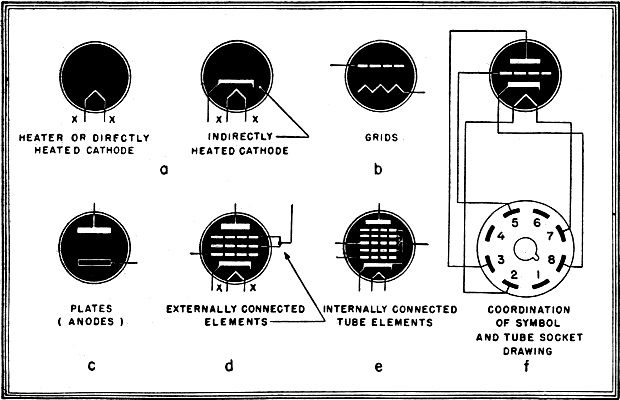
Fig. 1 - Standard methods of showing internal elements in tubes, also a tube base diagram. In reading or drawing radio schematic wiring diagrams, the tendency to ignore the drawn symbol and to rely upon the written designation to. explain the tube's function is very strongly manifested. The reason for this is obvious. Many technicians and engineers lack the practice to fully interpret tube symbols and thus gain the greatest efficiency and speed in working with blueprints. It is not always true that a tube symbol indicating a diode's function should be drawn as a diode. If the tube used is a 6Q7 and only the diode portion is used in the circuit application, the tube symbol must, none the less, be drawn representative of the 6Q7 tube. If a tube possesses two plates for full wave rectification and only one is used as shown by the schematic, the other cannot merely be left out of the symbol, it must be shown so that the engineer or technician can tell at a glance what type of tube is actually used and can quickly estimate its operating characteristics and circuit requirements. The unconnected elements of the tube should be terminated at the circle indicating the tube's envelope. By adhering to this method of direct representation, the possibility of errors getting by all concerned is greatly reduced. Careful use of tube symbols will also simplify the drawing of the necessary correlated tube socket, tube base, and wiring diagrams. If, for example, a 6X5 rectifier is drawn as a diode and marked 6X5, the reader of a schematic can usually identify the tube as possessing two plates. But if, by some error the legend "6X5" is not shown or is, accidentally written as "6Q7", the tube socket drawings, tube base diagrams and wiring diagrams may all be prepared for the 6Q7 tube's connections. Many headaches follow when eventually the error is discovered. If a tube symbol is drawn to represent a ,particular tube such confusion is reduced to a minimum. Many tubes which have their elements internally connected are used in present day circuits. Similarly, only certain elements of other tubes are actually wired to circuit components. These are factors which must not be ignored in drawing schematics. While it may not be essential to show unused elements and connections in a schematic they are definitely needed in wiring diagrams and tube socket drawings. As in most things this principle of adhering too rigidly to graphical symbolism can be overdone, There are only a few basic types of tubes although the tubes of each type may run well into the hundreds. The basic types have generally recognized symbols to represent them and if these few are studied and known they will serve to reduce the major problems arising from tube symbolism in radio circuit diagrams. The use of graphical tube symbols in actual wiring diagrams is not general practice. It is customary in this type of drawing to layout pictorially the tube socket with its pin -indicating numerals and draw the wires leading to them. In this pictorial work the possibility of confusion is very small. Wiring diagrams are usually used in conjunction with schematics and tube socket drawings. Tube socket drawings picture the tube base itself with call outs to indicate which prongs are "hot" and which are not used.
Fig. 2 - Symbols for the commonest types of tubes. Slight modifications are needed for others. The cathode-ray tube is also shown. The type of illustration shown in most tube manuals is not a true graphical symbol of the sort used in radio schematics. Rather, it serves to portray the elements of the tube in a simplified pictorial fashion and to indicate which tube base pins are connected to each of the tube's elements. Because of the diversity of types of drawings required on various blueprints to indicate a given tube, it follows that a graphical tube symbol is a cross between a pictorial portrayal of the tube and a symbolic semi-wiring diagram of the tube itself. At present we are concerned only with representative drawings of tube elements as they appear on a graphical symbol within the glass or metal vacuum envelope of the tube itself. This envelope is usually indicated by a circular or oval outline and the leads from each element are carried through this circle into the wiring of the schematic itself. It is not customary procedure to indicate on the schematic that the tube is either metal or glass. Many engineers, in drawing rough circuits, or to illustrate a point during discussions, will leave the enveloping circle of the tube's case off entirely, but in drawing a schematic to be used for production or design it is best to encircle the tube elements to avoid confusion. As any tube will contain at least two elements and even the most complex will be confined to grids, plates, cathodes and heaters in various quantities and positions, a primary requisite is the ability to identify each tube element as shown in the symbol. The "heaters" are usually drawn with no direct connections to their cathode. Standard methods of showing heaters are given on this page. Cathodes used in conjunction with heaters, and directly heated cathodes are also shown (Fig. 1-a). Plates (anodes) may be drawn in any one of several ways but the illustrations given here are customary methods of representation. The commonest of these are shown in Figs. 1-b and 1-c. A gas tube is always drawn with a distinguishing dot or circle within the tube outline and pilot lights or neon bulbs are drawn in such manner that confusion is impossible. When tube elements are connected within the tube the symbol is drawn as indicated in Fig. 1-d, but if elements are interconnected outside of the tube's envelope, even if the interconnections are in the pins, they must be drawn external to the tube symbol, as in Fig. 1-e. Television tubes are in a class by themselves. An example of a symbol for a television tube is shown in Fig. 2. The elements of these tubes, while similar to those of receiving and transmitting tubes, serve different purposes. Consequently the drawing of graphical symbols for television tubes should be treated and studied as a separate subject. In graphical tube symbolism, as in all schematic drawings of radio circuits, the important thing is to standardize. Standardization of all graphical symbols and of tube symbols in particular will repay the radio engineer, draftsman or technician a hundredfold in eliminated errors and in quicker, more ready interpretation of schematic drawings.
Posted August 23, 2021 |
|||||||||||||
 |
|||||||||||||
|
|||||||||||||


|
||||||||||||||||||||||||||||||||||||


