|
|||||||||||||
 |
|||||||||||||
Filter Building Made Easy |
|||||||||||||
Designing, building, and tuning low frequency filters is much easier for the person without a professional grade suite of software, fabrication, and test equipment than is RF / microwave frequency filters. Most of my design and integration work has been with system level transmit and receive racks for radar and satellite earth station installations, and typically for prototyping and/or very low quantity production. Accordingly, I often used connectorized components cascaded together where each functional block was predefined and tested. I would be handed a system input/output document that specified parameters for gain, phase noise, intercept points, noise figure, group delay, bandwidth(s), power levels, switching and settling times, current consumption, volume, weight, cost constraints, etc. That explains why my software offerings like RF & Electronics Symbols for Visio and RF Cascade Workbook all deal with system level design. On occasion, I needed to do some filtering at baseband, right in front of an A/D converter in order to whack interference getting into the signal path from ambient sources that ranged from non-compliant, unintentional RF radiators to noise spikes on power lines cause by nearby equipment switching. Filter Building Made Easy
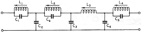
Fig. 1 - Circuit diagram of the filter discussed in the text. See Table I for sets of values for several cut-off frequencies in the audio range. Inexpensive Construction with Good Performance By Charles L. Hansen,* W0ASO The availability of ferrite-slug inductances offers the opportunity to make audio-frequency filters of good performance. Here is a practical method of constructing low-pass configurations such as might be used in low-level speech clippers. The experimenter often needs a good low-pass filter that will pass frequencies in the audio range up to a required cut-off point and provide 50 to 60 db. attenuation beyond cut-off. Commercially-designed units for carrier telephone application can be obtained, but usually cost thirty-five to one hundred and fifty dollars. Special filters designed to cut off to the purchaser's specifications, as well as commercially available filters, are priced beyond the reach of the average experimenter. The compromise method of making a filter out of power-supply chokes is frequently taken, but at the expense of performance in the final equipment. This is not very rewarding, to say the least. The purpose of this article is to describe a method of designing and building a sharp cut-off low-pass filter with components that are available from any well-stocked radio parts supply house. The passband and the sharp attenuation at the cut-off point of this home-built filter are comparable with and in many cases equal to commercial low-pass filters costing more than ten times the price of components used for this filter.
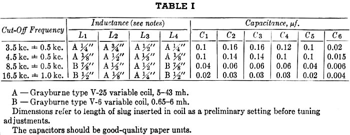
Table I - Filter component values A - Grayburne type V-25 variable coil, 5-43 mh. B - Grayburne type V-6 variable coil, 0.65-6 mh. Dimensions refer to length of slug inserted in coil as a preliminary setting before tuning adjustments. The capacitors should be good-quality paper units. Most articles on "how to design filters" deal with the mathematical derivation of the sections or meshes that make up the filter proper. After the filter has been designed mathematically and diagrammed, many experimenters have been disappointed in the actual performance of the completed filter. Because practical components fall short of the ideal reactances on which the filter formulas are based, as well as the difficulty of obtaining exact values, there is no substitute for practical experimentation with any filter, and the final values of capacitance and inductance may differ quite a bit from the calculated values. Also, most of us do not have the equipment, time, or inclination to design, build and adjust filters from theoretical information. With the availability of recently developed variable ferrite slug-tuned inductors1 good filters are now within the budget of everyone. Not only do we have an inductance that can be varied but we have the added advantage of a slug made of ferrite, which increases the Q by reducing the resistance per unit inductance. These inductances possess all of the qualities necessary for a good reactance which in turn results in the building of a good practical filter. A Practical Filter Design The configuration chosen for the filter described here and shown in Fig. 1 provides for a minimum of inductances. The filter contains two shunt m-derived half sections, one on each end, to provide a good impedance match from and to the flanking circuit units. An m-derived full section and a constant-k section make up the other two meshes. The m-derived section sharpens the cut-off characteristic and the constant-k section assures that attenuation of the unwanted frequencies beyond the passband will remain high. The impedance this filter must work into and out of is 500 to 600 ohms. Insertion of a filter into a circuit whose load impedance varies with frequency will result in erratic operation.
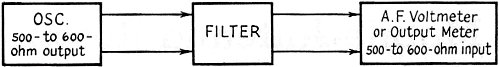
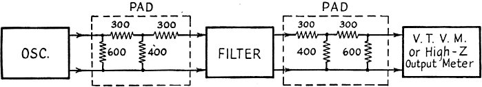
Fig. 2 - Test set-ups for adjusting filters. If equipment having output and input impedances matching the filter is available the simple arrangement shown above may be used; otherwise the use of isolating pads as shown in the lower drawing is recommended. Another alternative, when using an a.c. v.t.v.m., is to terminate the filter in its characteristic impedance, and adjust the input voltage to a fixed value for each frequency before making output measurements across the load resistance.
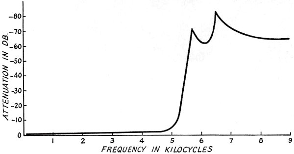
Fig. 3 - Measurements made by the author on a 5-kc. cut-off filter constructed from the data in Table I. Good practice in an extreme case of changing load impedances dictates the use of T pads connected before and after the filter. The use of these pads reduces the effects of source and load impedance variations with frequency. Table I gives practical component values for several frequency ranges. For example, if a low-pass filter having a cut-off of about 5000 cycles is needed, a set of values will be found in the second row. Wire the condensers and inductances as shown in Fig. 1 and adjust the ferrite slugs to the specified distances. Connect the completed filter to an oscillator and a measuring set having 500- to 600-ohm impedance. If an oscillator and measuring set with this impedance value are not available use a pad set-up as shown in the lower drawing of Fig. 2. Manually sweep the oscillator through the passband and check the uniformity of response with the output meter or measuring set. Also check for the correct cut-off frequency of 5000 cycles. Adjust the slugs on L2 and L3 alternately to place the cut-off frequency at the desired frequency. Manually sweep through the passband again and adjust the slugs on L1 and L4 for improvement in the smoothness of the passband. These operations should be repeated until the passband response is reasonably flat (within 0.2 db.). The frequencies beyond 5700 cycles should be attenuated 60 db. or more, with an attenuation peak of 70 db. or so at 6500 cycles. After adjustment the filter is ready for use. It may be enclosed in a metal box taking up no more room than an average 20-watt output transformer. The individual sections may be shielded from each other if desired. Among the many applications that can be thought of for such filters are (1) speech filters in communication work; and (2) audio use in recording and high-quality home systems (see Audio Engineering for several discussions). For example, a 5000-cycle filter can be used for sharply cutting off the hiss and scratch from old records. 1 The ones used by the author are made by the Grayburne Corp., 4-6 Radford Place, Yonkers, N. Y.
Posted September 28, 2022 |
|||||||||||||
 |
|||||||||||||
|
|||||||||||||

|
||||||||||||||||||||||||||||||||||||


