|
|||||||||||||
 |
|||||||||||||
The Tube Family Tree, Part 2
|
|||||||||||||
What is capable of putting out more power, a solid state amplifier or a vacuum tube amplifier? The simple answer is that given a large enough array of power combiners, a solid state power amplifier can theoretically put out as much power as a tube amp, but the complexity is much, much greater. A single vacuum tube can output RF power levels in the megawatt range, but even the highest power GaN (gallium nitride) semiconductor devices do not reach the kilowatt realm. That is the reason there are still so many vacuum tube transmitters - the tubes themselves - still being produced today. Equivalent size solid state transmitters are generally much larger because of the huge number of individual power amplifier modules and massive power combiners needed. The great advantage of solid state PA (SSPA) systems is the elimination of a single point failure. Output power is degraded gracefully rather than catastrophically and maintenance is vastly simpler since most individual SSPA modules are hot-pluggable, meaning the system continues to operate in a crippled state while failed parts are replaced. There is no new technology on the horizon that will change the equation, but don't be surprised if some form of graphene surfaces as the new wonder power amplifier material. Here you can read Part 1, Part 2 and Part 3. The Tube Family Tree, Part 2
By Louis E. Garner, Jr. In the early days of radio, essentially the same tubes were used for both transmitters and receivers. Even today, although transmitting tubes are considered a distinct class, there is a considerable overlap between higher power receiving and lower power transmitting tube types - in construction, in design, and in electrical characteristics. Hams, for example, frequently use receiver power tubes, such as the 6L6, in their radio transmitters. The low-power transmitting tube does not differ appreciably in appearance, size or power-handling capacity from the tubes used as horizontal deflection amplifiers in television receivers. There is also a good correlation between transmitting and receiving tubes as far as generic types are concerned. Both classes can be divided into such groupings as diodes, triodes, tetrodes, pentodes, and beam power tubes. Both filamentary and indirectly heated cathodes are used in each class. The tube electrodes have the same designations - plate, grid, cathode, and so on - in both. And the same general characteristic terms are used in describing both. When we turn to specifics, on the other hand, we find that there is a considerable difference between transmitting and receiving tubes. Transmitting types, in general, are constructed of sturdier materials, and, as a result, are larger, heavier, and more expensive than their receiving type counterparts. Two extreme examples may be helpful.
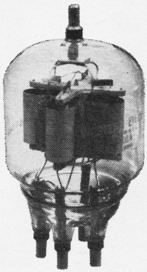
This is a typical transmitting tube, by Westinghouse. Plate is made of graphite.
Components of a high-power Federal Telephone & Radio transmitting tube. Electrodes are heavy and special insulation is used to withstand high voltages and heat; heavy-duty terminals take care of high currents. Tubes of this general type may be forced air-cooled or water-cooled. (above and below left)
Designed for forced air-cooling, this Amperex high-power transmitting tube has a finned radiator fitted over the plate.
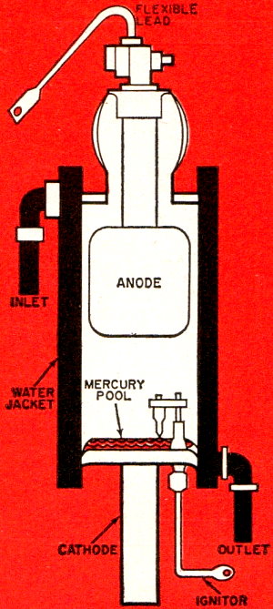
Multiplier-type phototube. General Electric version. The 6AQ5 is a typical beam power receiving tube, while the RCA 2039 is a high-power shielded-grid beam triode transmitting tube. The basic specifications of the 6AQ5 include: filament voltage, 6.3 volts; filament current, 0.45 amps; peak positive-pulse plate voltage, 1100.0 volts; peak plate current, 0.115 amps; average plate current, 0.040 amps; and plate dissipation, 10.0 watts. The same basic specifications of the 2039 are: filament voltage, 7.3 volts; filament current, 1140.0 amps; peak positive-pulse plate voltage, 40,000.0 volts; peak plate current, 92.0 amps; average plate current, 5.7 amps; and plate dissipation, 150,000.0 watts. These comparative specifications emphasize the primary difference between transmitting and receiving tubes: their power-handling capacity. To obtain high powers, very high voltages and currents are required. This means that the tube's electrodes must be very heavy in order to handle the large currents without melting, and widely separated to prevent arcing at the high voltages. (Arcing can destroy a tube.) Special insulation must be used where the electrodes are mounted to withstand a combination of high heat and tremendous voltages. And, of course, heavy-duty terminals are needed to handle the currents. Finally, all of the above construction factors must be taken into account and balanced against the tube's designed operating frequency (which may require close spacing) and desired electrical characteristics. While maximum electrical ratings, amplification factor, mutual conductance, and similar characteristics are all important, the transmitting tube's most important single characteristic is probably its rated maximum plate dissipation. Specified in watts (or kilowatts), this is directly proportional to the amount of power that the tube can handle and hence the r.f. power it can deliver. In practice, the tube's actual plate dissipation is the difference between its d.c. plate input power (plate voltage multiplied by average plate current) and its r.f. output power. For example, if a Class C r.f. power amplifier is 70% efficient and has a d.c. input of 10 kw. (5000 volts at 2 amperes, say), it will deliver 7 kilowatts r.f. (approximately) and will have a plate dissipation of 3 kw. With plate dissipations running into the kilowatt range for some types of tubes, it is obvious that a means must be provided for removing the heat generated if the tube is to be kept from melting. While lower power transmitting tubes are invariably convection air-cooled, higher power types are either forced air-cooled or water-cooled. Medium-power tubes are often provided with radiating fins, while high-power types are equipped with water jackets. The cooling device, whether a radiating fin system or a water jacket, may be either an integral part of the tube or a separate accessory. Industrial Tubes. Except for a few special types, industrial electron tubes correspond in most ways to their receiving and transmitting tube counterparts. Low-power receiving types are used in industrial controls, alarm circuits, counters, protection devices, and similar equipment, while transmitting types are found in high-voltage and high-current power supplies, welders, and induction and dielectric heaters. In general, industrial receiving type tubes, while basically similar to ordinary receiving tubes, are usually of sturdier construction and designed for continuous operation under rigorous physical conditions. Industrial tubes, as a rule, must have extremely long filament life, for equipment shutdowns - even for short periods - can be extremely costly to a manufacturer. In addition, the tubes must be able to withstand extremes in temperature, shock, and vibration. Gas-filled tubes are used extensively throughout industry. Thyratrons and cold-cathode tubes are utilized for motor, electromagnet, and solenoid control, while mercury vapor rectifier tubes are employed in heavy-duty d.c. power supplies for electroplating, electrolysis, and similar work. There is one type of electron tube that is used in many industrial applications but which is not, however, found in communications equipment: the ignitron. Used for high-capacity switching and in heavy-duty d.c. power supplies for welding, motor control, and certain electro-chemical processes, the ignitron is basically a special type of cold-cathode tube in which mercury vapor is produced by a controlled electric arc. In one sense, it is a type of rectifier. Some types are capable of handling voltages as high as 20,000 volts and conducting currents as great as 35,000 amperes for short periods. In its basic form, the ignitron consists of an evacuated metal envelope (which may be double-jacketed for water cooling), a pool of mercury which serves as a cathode, a heavy metal anode, and a special ignitor of rough-surfaced material which resists "wetting" by the mercury but which projects into the pool of liquid metal. In operation, the tube will not conduct until "fired" by current applied to its ignitor electrode. A moderate-current pulse here creates high-current densities at the rough points of contact with the mercury pool, establishing a hot arc which vaporizes the mercury, filling the tube with vapor and allowing conduction to take place between the cathode and anode. Afterwards, the anode-cathode current is sufficient to keep the arc established and to maintain current flow. Phototubes. When light falls on certain metals and metallic compounds, such as cesium, cesium oxide, potassium, and zinc, electrons are emitted from the material's surface. This photoemissive effect was first noticed, although not fully understood, by Heinrich Hertz in 1887. Like many early discoveries, this one eventually led to the development of the phototube: a light-sensitive electron tube with an electrical output proportional to the amount of light falling on its sensitized surface. Phototubes are used extensively in both industrial and commercial applications - burglar alarms, automatic door openers, electronic counters, doorway annunciators, safety equipment for industrial machines, sound motion picture projectors, etc. The phototube is a special type of cold-cathode diode. The cathode is generally a semicircular metal plate coated with photo emissive metallic compounds, the plate a small rod or wire. In operation, light falling on the cathode causes electrons to be emitted. If a positive voltage is applied to the plate (or anode), these free electrons migrate to it, producing a minute output current. Like human eyes, phototubes differ in their response to light. While their current output is directly proportional to light intensity, the current may vary considerably with identical light levels in different colors. Depending on the types of photoemissive compounds used, phototubes may be made more sensitive to infrared, ultraviolet, or to the whole spectrum of visible light. Except for physical construction and type of lead connections, the chief differences between phototubes are found in their spectral responses. Sometimes, a small amount of selected gas will be introduced in a phototube. The gas ionizes and reduces the tube's internal cathode-anode resistance, permitting it to deliver a greater current output for a given cathode illumination. Gas phototubes have a higher sensitivity than high-vacuum types but are more easily damaged by excessive voltages and are somewhat less stable. Photomultipliers. Unfortunately, the current output of standard phototubes is extremely small - on the order of a microampere or less at typical illumination levels. This fact has led to the development of a class of special phototubes called photomultipliers. Used in scintillation counters, automatic light dimmers, and in similar applications, photomultipliers make use of the principle of secondary emission (which we discussed in Part 1) to increase their current output. The photomultiplier consists of a photoemissive cathode, a series of secondary anodes called dynodes) and the output anode or plate. Depending on tube type and physical design, the dynodes may be arranged in a circle around the cathode, or in parallel lines behind the cathode, which is tilted at a small angle.
In electrostatic cathode-ray tubes, the electron beam is deflected and focused by the internal elements.
Details of the ignitron are shown above.
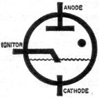
Schematic symbol for this industrial tube.
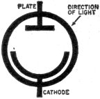
Basic phototube symbols. At left: the standard version. At right: a photomultiplier.
A typical phototube, by General Electric./td> Cathode-Ray Tubes. By definition, a cathode-ray tube (CRT) is a device which utilizes cathode "rays," i.e., "rays" emitted by the device's cathode. Cathode rays are, of course, streams of electrons. Although often considered a relatively modern invention, cathode-ray tubes are, historically, even older than more familiar electron tubes. Various types of cathode-ray discharge and display tubes were used extensively in physics laboratories and schoolrooms before the turn of the century, and as early as 1897 Karl Braun developed a cathode-ray display tube very similar to modern television tubes. TThe "heart" of most present-day CRT's is the electron gun. The gun is made up of a filament, an indirectly heated cathode, a disc-shaped control grid, and disc- or cylindrical-shaped focusing and accelerating grids (or anodes). Its purpose is to produce a sharp stream of accelerated electrons. The number of electrons in the stream (and hence its intensity, as well as the brightness of the spot it produces when it strikes a screen) is controlled by the voltage applied to the control grid. The beam's sharpness of focus is determined by the voltage relationships between the focus and accelerating anodes.
In electromagnet CRTs, the beam is focused and deflected by magnetic fields set u around the neck. Display Tubes. Direct descendants of the early Braun tube, display CRT's are used extensively in TV receivers and monitors, oscilloscopes, radar equipment, and in a variety of test and research instruments. As the name implies, these tubes serve to display electrical phenomena on a fluorescent screen, either as a line, pattern, or reproduced picture. In general, display tubes are made up of an electron gun assembly, a means for focusing (if not contained within the gun itself) and deflecting the electron beam, and a fluorescent screen. Manufactured in sizes ranging from tiny units with a 1" -diameter screen to giant picture tubes with 30" screens, they are usually funnel-shaped. The screen itself may be round, square, or rectangular. The envelopes or "funnels" are made either of metal or glass, or a combination of both. Most display tubes are identified by a combination numeral-letter type number. The first number indicates the nominal size of the tube's screen, the first letter (or letters) the particular tube, and the last letter and numeral the type of fluorescent material (or phosphor). Phosphors. Typically, a type 5BP1 tube has a 5" screen with a type "P1" phosphor. Similarly, a type 20DP4 has a nominal 20" screen and a "P4" phosphor. Cathode-ray tubes used as TV picture tubes generally have rectangular screens and their size designation refers to a diagonal measurement across the face of the tube. In some cases, TV picture tubes are called kinescopes. An arbitrary system is used for identifying the various phosphors used. A type P1 phosphor, for example, has green fluorescence and medium persistence; you'll find this type in most oscilloscope tubes. Type P4 phosphors have white fluorescence and medium persistence, and are employed primarily in television tubes. Type P5 phosphors have a bluish-white fluorescence and very short persistence; tubes with this type of phosphor are used for high-speed photography of electrical phenomena having a short time duration. The P11 phosphor is similar to the P5 type, but has a slightly longer persistence. Types P7 and P14 are both two-layer phosphors. The P7 type has a long persistence, first emitting a bluish light, then a greenish-yellow. The P14 type has medium persistence, first emitting a bluish, then an orange light which persists for over a minute. These two types of phosphor are useful in instruments employed to observe low-speed recurrent and non-recurrent phenomena. The last type of phosphor, P15, has a very short persistence in the near ultra-violet region, emitting a visible blue-green light afterwards; its principal application is in flying-spot scanner tubes. Electrostatic and Electromagnetic. Electrostatic CRT's are those which employ electrostatic fields to move the electron beam obtained from the gun assembly. Electron beams may also be deflected by magnetic as well as electrostatic fields, however. Most TV picture tubes are electromagnetic types. In many cases, the beam may be focused as well as deflected by magnetic fields, with a permanent magnet or electromagnetic coil placed around the tube's neck near the gun assembly. In some tubes, the electron gun is aimed at an angle, rather than straight towards the center of the screen, so that gas ions (in the cathode beam) which may be produced are sent to one side and do not strike the screen (where they could cause a damaging "burn"). Where this technique is used to "trap" ions, a separate ion trap magnet restores the lighter electron beam to its straight-line path before deflection. Some CRT's combine the basic operating features of both electrostatic and electromagnetic types. Electrostatic focusing may be employed, for example, by using a suitable electron gun, with electromagnetic means used for deflecting the beam. Cathode-ray tubes designed for color television receivers are basically similar to the tubes described above, except that several electron guns are employed and a special screen is used which fluoresces in the three primary colors: blue, green, and red. The screen itself is made up in a repetitive triangular pattern of small phosphor dots and protected by a mask, aligned so that each of the electron guns excites only its particular phosphor (blue, green, or red). Flying-Spot Scanner. The flying-spot scanner is a special type of display tube, similar to more conventional CRT's except for its phosphor. In general, it is used in conjunction with picture transparencies (such as motion picture film or slides) and a phototube to produce a sequential electrical signal (or video signal) which can be televised or used to reproduce the original picture. In operation, a raster, or rectangular light pattern of fixed intensity, is formed on the flying-spot scanner's fluorescent screen as the spot of light produced by the electron beam "flies" across the screen. This moving spot of light is transmitted through the transparent film to the phototube, where it develops a varying electrical signal, dependent on the film emulsion density at each spot and hence on picture content. The video signal obtained from the phototube is similar to that produced by a TV camera and is used in the same way. (to be continued)
PostedNovember 30, 2021 |
|||||||||||||
 |
|||||||||||||
|
|||||||||||||


|
||||||||||||||||||||||||||||||||||||


