|
|||||||||||||
 |
|||||||||||||
The Electronics of Fluorescent Lamps
|
|||||||||||||
Before there were CFL light bulbs with complicated electronic circuits for generating the requisite high voltages without a transformer, there were just the familiar straight (and sometimes circular) fluorescent bulbs that use a simple ballast arrangement and a built-in switch in the bulb base. As with compact fluorescent (CFL) lights, very few people understood how they worked. Most knew that the 8-foot-long T-12 bulbs (the large diameter ones used in commercial buildings) made a really cool implosion sound when they broke - usually intentionally (by people like me) since the glass tubes are amazingly tough. I remember many moons ago, between high school and the time I enlisted in the USAF, while I was an apprentice electrician working on a renovation job at a public school (I took electrical vocational courses for 3 years in high school), a co-go-fer and I spent weeks wiring fluorescent fixtures all throughout the building. We worked atop a tall scaffolding that was on wheels, pulling ourselves around the room by grabbing the suspended ceiling grid. When the foreman wasn't around, we relieved our utter boredom by "accidently" dropping the fluorescent bulbs onto the concrete floor. If done just right so that the bulb hit the floor in a perfectly vertical position, it would bounce up two or three feet and implode in mid-air. The acoustics of the big, empty room, devoid thus far of sound-absorbing ceiling tiles, really enhanced the effect... but I digress. This article does a nice job of explaining how the non-curly-Q fluorescent bulbs work - with and without external starters. The Electronics of Fluorescent Lamps
Fluorescent lamps, once a novelty, are now an accepted part of the American scene. Their gentle blue-white glow is encountered everywhere, from the tops of skyscrapers to the depths of the New York subway system. However, the operating principles of fluorescent lamps are little understood even by technicians. Invisible Light. Many people know that fluorescent lamps are among our most efficient light producers, and that they operate with a mercury vapor arc. But few realize that over 80% of the radiation produced by that arc is in the ultraviolet region and invisible to the human eye, and that every effort is made to keep as much energy as possible in the invisible ultraviolet end of the spectrum. Sounds foolish, doesn't it?
Cutaway view of a fluorescent lamp. All fluorescent lamps are constructed as shown here. Only the glass tube changes in size and shape from model to model. The visible light actually comes from chemical compounds coated on the inside of the glass tube. Called phosphors, these compounds have the property of emitting visible light when they are excited by ultraviolet radiation. They have been termed "light transformers" because of their ability to absorb energy at one wavelength and radiate it at another. The fluorescent lamp depends upon ionization for the production of the necessary ultraviolet arc. Here's how it's done. The free electrons in the gas are accelerated by an applied voltage, and each time a collision occurs between an electron and a gas molecule, one or more additional electrons are displaced. These electrons in turn, are accelerated enough to repeat the process on other molecules, and a chain reaction takes place. As each molecule returns to a stable state, it gives off its excess energy in the form of radiation. It's the frequency of the radiation that determines whether visible or invisible light will be obtained. In commercial lamps, the pressure of the gas sealed in the lamp is adjusted very carefully so that nearly all of the radiation occurs at one given ultraviolet wavelength, 2537 Angstrom units. This frequency is selected for optimum excitation of the tube's phosphor coating. Each chemical compound in the phosphor coating radiates light at a certain wavelength. For instance, zinc silicate releases its radiation as green light, cadmium borate radiates a predominately pink color, and calcium tungstate when excited gives off blue light. By carefully blending these and other compounds, almost any desired color can be obtained. Warming to the Job. The electrons required to facilitate the starting of the arc are provided by coated tungsten filaments in the ends of the fluorescent tube - similar to the filament in an ordinary vacuum tube. Once the arc is achieved, the heated filaments are no longer required and are automatically switched off. A small amount of argon or krypton gas present in the tube facilitates the initial arcing, which also serves to evaporate the globule of mercury in the tube. From this point on, the arc is basically mercury vapor. There are two pieces of auxiliary apparatus necessary to operate a fluorescent lamp. One of these is a starter which acts as the automatic filament circuit switch mentioned above. The second additional element required is the ballast, which serves as a choke coil to regulate arc current as well as an autotransformer to provide the high voltage kick needed to start the arc. An Inductive Kick.
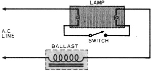
Fig. 1. Basic fluorescent lighting circuit in general use only on small desk lamps. A manual switch performs the starting function.
Fig. 2. This circuit is sometimes used to correct the poor power factor in the circuit of Fig. 1. The ballast is shown here functioning as autotransformer as well as choke coil. The basic lamp circuit is shown in Fig. 1. When the switch is closed, the ballast and the two filament windings are placed in series across the applied voltage, and the filaments heat. When the switch is released a moment later, the inductive kick of the iron-core ballast coil causes a momentary voltage surge across the lamp which starts the arc. As the ballast is now in series with the lamp, the arc current is limited by the impedance of the ballast. This simple circuit is widely used on small desk lamps, but has too many disadvantages for general lighting use. One of the disadvantages of the single lamp circuit is its poor power factor. As the circuit is primarily inductive, due to the ballast, the current and voltage have a phase relationship which makes for inefficiency in light output compared to current drawn. A partial solution to this problem is the circuit shown in Fig. 2. Here the starter is an automatic device although its function is the same as the switch in Fig. 1. The power factor in this unit is improved by a shunt capacitor. As a capacitor and a coil have an opposite effect on power factor, one offsets the other; and the resistor serves to bleed off any charge which remains on the capacitor. The circuit of Fig. 2 has been drawn to indicate that the ballast is also serving as an autotransformer. The number and size of the lamps used determines whether this is necessary or not. Factors and Flickers. Another objectionable feature of the single lamp circuit is its flicker, due to the 60-cycle line. Since incandescent lamp filaments operate at a very high temperature, there isn't time for them to cool sufficiently from cycle to cycle for the variation of light to be seen. The fluorescent lamp must extinguish and restrike its arc 120 times per second as the voltage reverses polarity. This causes a disturbing stroboscopic effect around machinery with cyclical motion. Probably the most common circuit in use today is shown in Fig. 3. This is a two-lamp circuit and corrects several of the disadvantages inherent in single lamp setups. The lamp indicated as inductive is connected in the same way as the lamp in Fig. 1. The other lamp, however, has a capacitor in series with its ballast. This serves to change its phase relations so that its current leads rather than lags the voltage, and corrects the overall power factor. Thus, the two lamps operate more efficiently as a unit.
Fig. 3. For the control of two lamps, this circuit is in wide-spread use and has excellent power factor characteristics.
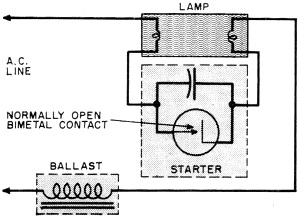
Fig. 4. Typical glow-type starting circuit used in home-type fluorescent circuits.
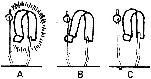
How a Glow Starter Works The addition of this series capacitor, though, produces another problem. When starting, the capacitive circuit sometimes limits the current required to preheat the filaments. This effect is overcome by adding another compensating coil in series with the starter on this lamp only. Use of this type of two-lamp circuit is also beneficial in overcoming flicker. Because the lamps operate out of phase, they reach their peaks of illumination at different times and the combined light is relatively free from disturbance. The Starter Story. One of the most fascinating pieces of auxiliary equipment is the fluorescent starter. Its task is to close the circuit containing the filaments when voltage is first applied, and after a preheating period of several seconds, to open the filament circuit and keep it open as long as the lamp remains on. A bimetallic strip is used which bends when heated, and serves as sort of a time switch. The most common type of starter is the glow starter. The entire unit is sealed within a small glass envelope containing neon or argon gas and connected as shown in Fig. 4. A bimetallic strip controls a contact which is normally open. When first turned on, the full line voltage is applied across the glow lamp, causing the gas to ionize and conduct. The heat of the ionized gas is sufficient to cause the bimetal strip to close the filament circuit. The contact closing shorts out the glow discharge and the bimetal begins to cool. After cooling (which takes long enough to preheat the filaments satisfactorily), the contact within the starter opens and the fluorescent lights. The starter is now across the lamp voltage, which is not enough to ionize the neon gas, and so the unit is inoperative as long as the lamp remains on. The glow-type starter consumes no energy from the circuit after the starting period is over. Its timing is not accurate, however, and as it is difficult to maintain the proper gas pressure over a long period, sometimes the timing tends to become very erratic. The line voltage produces a glow discharge between the bimetallic strip and the fixed contact (A); the heat from the glow actuates the bimetallic strip, the contacts close and the filament preheating begins (B); this shorts out the glow discharge, the bimetallic strip cools and the contacts open (C). The resulting inductive kick from the ballast then starts the tube. A great many of our present-day starters incorporate modifications such as a manual reset. If the lamp does not light after repeated attempts by the starter, it ceases functioning until the trouble is corrected and the starter is reset by pushing a spring-loaded button. There are others that use different contacts for restarting so that it isn't necessary to wait for a bimetal strip to cool completely before it can recycle. The starter shown in Fig. 4 also contains a capacitor across the lamp contacts, which acts to suppress radio interference. Manufacturers of fluorescent lamps publish handbooks which elaborate on these principles. They also give many more lighting circuits and their applications. The very fact that fluorescent lamps are so readily accepted and so seldom studied in detail is in itself a fine tribute to their efficiency and dependability.
Posted November 22, 2021 |
|||||||||||||
 |
|||||||||||||
|
|||||||||||||


|
||||||||||||||||||||||||||||||||||||


