|
|||||||||||||
 |
|||||||||||||
Finding Relay Operate and Release Times
|
|||||||||||||
Sometimes, component datasheets can be pathetically lacking in detail for parameters that you might think would be a minimum amount of information needed in order to integrate the device into a circuit or system. Or, it may be that you found a part in a spare parts box and can't find a datasheet for it. When those times come, it is necessary to characterize the part yourself. Relay control really isn't rocket science when it comes to electrical circuits, but there are a few rules of thumb that should always be observed, the most important of which (other than not exceeding voltage and current maximums) is to wire a diode reverse biased across the coil terminals so that the voltage/current induced due to the field collapse during de-energizing does not smoke the driver circuit. This article from the April 1967 edition of Electronic World magazine recommends a test setup for determining the cut-in and cut-out speeds. It might be important to know the speed in case the application has a timing requirement for synchronization with another part of the circuit/system. Here are links to the other relay articles: Operate and Release Times of Relays, Reed Relays, Time-Delay Relays, Finding Relay Operate and Release Times, Arc, Surge, and Noise Suppression Finding Relay Operate and Release Times By Donald Ludwig
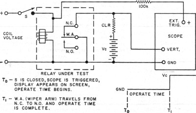
Fig. 1 - Circuit used to find operate time of relay along with oscilloscope display that is produced with setup.
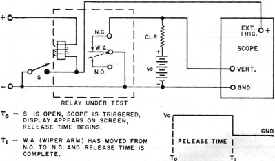
Fig. 2 - Circuit used to find release time of relay. The values of CLR and Vc depend on particular application. When designing circuits using relays it is often necessary to know the relay's operate and release times. Because of certain circuit conditions, the times given by the manufacturer will not always hold true. The method to be described will help establish these parameters and requires only a regulated power supply, a single-trace oscilloscope, and two simple circuits - as suggested by the National Association of Relay Manufacturers. This article illustrates the standard s.p.d.t. break, make Type-C relay under test. This type of relay is frequently used and the circuits employed can easily be converted to test other types of relays. Operate time begins when the energizing voltage is applied to the relay coil and ends when the wiper arm has reached the energized (N.C.) position. See Fig. 1. Release time starts with the removal of the energizing voltage from the coil and ends when the wiper arm has returned to the de-energized (N.C.) position. See Fig. 2. The checks should be made under conditions closely approximating actual operating conditions. These include temperature, mounting position, use of arc suppressors, and any other circuit conditions that may affect operate and release times. It should also be remembered that the accuracy of the test is dependent on the accuracy of the scope, if all other precautions are taken. If the relay being tested has more than one set of contacts, the operate and release times of each set being used should be checked. The time required for each set of contacts to function may differ from one set to another. An increase in coil temperature due to repeated operations of the relay may cause the resistance of the coil to change and affect the time elements of the relay. Each set of contacts should be checked several times before calling the test conclusive. When determining relay operate and release times, the scope's sweep speed should be set with a time base which will permit viewing of the waveforms and still allow accurate readings to be made. This method requires no elaborate equipment to establish the relay's operate and release times. Using an oscilloscope also permits contact bounce to be examined.
Posted November 25, 2019 |
|||||||||||||
 |
|||||||||||||
|
|||||||||||||

|
||||||||||||||||||||||||||||||||||||


