|
|||||||||||||
 |
|||||||||||||
|
Electricity - Basic Navy Training Courses NAVPERS 10622 |
|||||||||||||
|
Here is the "Electricity - Basic Navy Training Courses" (NAVPERS 10622) in its entirety. It should provide one of the Internet's best resources for people seeking a basic electricity course - complete with examples worked out. See copyright. See Table of Contents. • U.S. Government Printing Office; 1945 - 618779
Chapter 14 Chapter 14 GENERATORS ELECTRICAL PUMPS The modern fighting ship consumes a tremendous
amount of electrical energy. The electrical machinery furnishes her men with food,
water, and fresh air. Her nerves are electrical wires coordinating all her activities,
all her power, to make her a fighting machine.
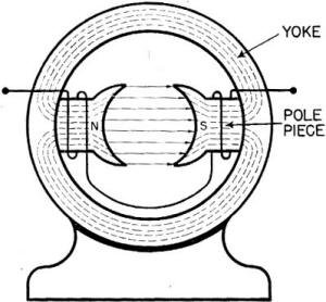
Generators - the engines of induction - are electrical pumps. They force electrical energy through the ship - from her stem to her stern. Although generators are SIMPLE IN PRINCIPLE - mutual induction machines - they are sometimes COMPLEX IN DESIGN. When the design of a generator seems unnecessarily complicated, just remember that it was built to do a job. And that job has certain requirements. If the only way to meet the requirements is by complicating the machinery - then it's going to be complicated. You don't handle a racing boat like you do a fishing tug. HOW A GENERATOR IS BUILT Since a generator is a mutual induction job, its first requirement is a magnetic field. The simplest generator field is built like the drawing in figure 121. Two electromagnets are mounted in a circular , iron frame called a YOKE. These electromagnets are wound so as to produce opposite polarity. notice how the magnetic circuit is entirely in iron except . at the center, between the poles. This area - between the pole pieces - is the only part of the field outside the iron.
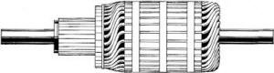
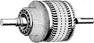
Figure 121. - Generator-magnetic field. The yoke, its pole pieces, windings, and the field produced are the primary circuit. The secondary circuit is a coil wound on an iron core. The coil and core, mounted on a shaft is the ARMATURE. Figure 122 shows a typical armature. To make the generator complete, the armature of figure 122 fits into the area between the pole pieces of figure 121. HOW IT WORKS The frame of the generator stands still - the field of flux is steady and stationary. But; the armature shaft is rotated by a source, of mechanical power - the PRIME MOVER. And as the armature is rotated, the conductors of the coil cut through the field flux. As in the simplest, or the most complicated, system, conductors cutting flux produce an induced voltage.
Figure 122. - Generator-armature. These are the elements of a generator -
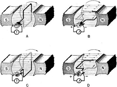
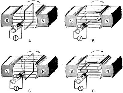
UNDERSTANDING the ACTION The easiest way to understand what happens in an armature, is to lift ONE TURN of the coil off its iron core and study it alone. Figure 123 is a single turn rotating in the magnetic field. The coil is shown in four positions which represent one complete revolution of the coil. In A the coil is producing zero voltage - the galvanometer reads zero. It's zero, because, in this position, the coil is cutting NO flux. How can a coil move in a field and yet cut no flux? By moving parallel to the lines of force. notice in A that both sides of the coil are moving in a straight line between the poles. When conductors are moving this way they slip between the "rubbery" lines of force and do not break them.
Figure 123. - Armature coil revolving in magnetic field. In B the coil has moved to a position at right angles with A. Now the black
side of the coil is cutting DoWNWARD and inducing a voltage OUT. And the white side
is cutting UPWARD and inducing a voltage IN. The galvanometer attached to the two
terminals of the coil deflects. Trace this circuit through. notice that although
the two induced voltages are opposite - one in and the other out - the voltage for
the TOTAL coil is the ADDITION of these two. Trace the current through the coil
- you go WITH both voltage arrows. This means that both voltages add force to the
current.
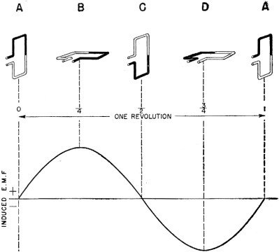
the COMMUTATOR It's proved that rotating coils produce alternating current. But - go back to
figure 123 and check up on those galvanometer readings. How about it? In both Band
D the deflection is toward the right. This indicates that DIRECT current - is flowing
OUTSIDE the coil. How come - A.C. inside the coil and D.C. outside? The a.c. has
been RECTIFIED - that is, changed from alternating to direct current. The COMMUTATOR
did the job.
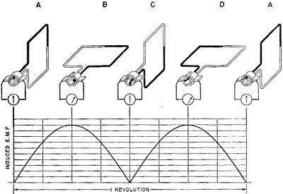
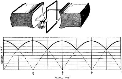
SLIP RINGS - A.C. Instead of connecting a rotating coil to a commutator, connect each terminal of the coil to a SLIP RING. Slip rings are simply smooth rings of good conductor material. Now brushes riding on these slip rings will pick up a.c. and deliver it to the external circuit. Figure 124 shows a rotating coil with slip rings attached.
Figure 124. - Slip ring coil revolving in magnetic field. Starting with A, the coil is in the neutral plane - no induced voltage. In B, the coil is at right angles to the flux. The induced voltage in the BLACK side of the coil is OUT. In the WHITE side, it is IN. SO you call the white ring POSITIVE and the black ring NEGATIVE. In C, the coil is again in the neutral plane. In D, the coil is once more cutting flux at right angles. But, now the induced voltage in the BLACK side is IN. And in the WHITE side, it is OUT. Now, you call the white ring NEGATIVE and the black ring POSITIVE. This means that through one half of the revolution the white ring is positive and through the other half it is negative. The same is true of the black ring. Consequently the current in the external circuit reverses itself every time the coil current reverses. And the reverses occur every time the coil passes through the neutral plane.
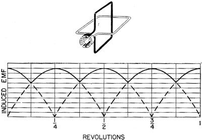
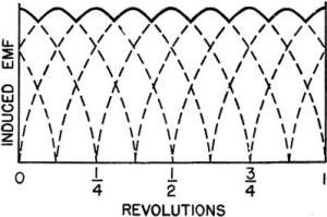
Figure 125.-Graph of alternating EMF. SUMMARY OF D.C. AND A.C. All coils, rotating in a magnetic field, have a-c voltage induced. This a.c.
can be connected directly to an external circuit by means of slip rings. Or, it
can be rectified by means of a commutator in order to deliver d. c. to the external
circuit.
Figure 126 is a graph of d-c voltage. Again the small coil's position, corresponds
to the voltage indicated.
Figure 126.-Graph of direct EMF. You should recognize the two graphs of figures 125 and 126 as typical graphs of alternating current and pulsating direct current. Graphs of these two types of current always have the general shapes of these figures. MANY COILS A single coil rotating in a magnetic field is like an 8-cylinder job hitting on only one. The output power is weak and fluctuating. Fluctuation is a characteristic of a.c. And adding more coils does not eliminate the regular rise and fall of a-c voltage. But adding more coils to a d-c job smooths out the fluctuation and changes the direct current from pulsating to regular d.c.
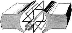
Figure 127.-Two coil armature. Here is how it works. In building up an armature from one to many coils, first add one more coil at right angles to the first. Figure 127 shows the two coils arranged on an armature at right angles to each other. When this armature is rotated, the black coil is going to be one-quarter of a revolution behind the white coil. Which means that the induced voltage of the black is at zero value when the white is at maximum value. notice that a four segment commutator is required for the terminals of the two coils. Brushes riding on this commutator contact ONLY the coil producing the BEST voltage. Figure 128 is a graph of the volt-ages produced by both coils. The heavy part of the graph is the voltage picked up by the brushes. This is the voltage delivered to the external ciruit. notice that the voltage is more level than it was with one coil. True, it still is a pulsating voltage - but now it doesn't go all the way down to zero. Adding the extra coil has taken out some of the "bumps."
Figure 128. - Two coil voltage. Add two more coils, placing them midway between the original coils on the armature.
Now you have a generator like figure 129. Figure 130 shows the voltage produced
- by this four coil job.
Figure 129. - Four coil armature.
Figure 130. - Four coil voltage. The gramme ring armature does a whale of a lot that the one, two, or four coil jobs did not do. FIRST - the coil is wound on iron. This reduces the reluctance of the magnetic circuit by eliminating almost all the air gap. Consequently, a stronger field and a higher induced voltage in the armature. SECOND - the windings are in series - the individual voltages of the 'turns add together. Consequently, a higher voltage at the terminals of the generator. THIRD - the coils form TWO paths between the brushes - one path up either side of the ring. Therefore, this armature can carry more current without overheating.
Figure 131. - Gramme ring armature. Suppose you follow one ampere of current through this generator. Entering the
commutator at the positive brush, the current can only go into ONE segment because
all the segments are insulated from each other.
Figure 132. - Drum wound armature. Again, series connections and many coils. The principal advantages of the drum winding lie in (1) the saving of wire, (2) the reduction of reluctance, (3) the ease of repair. In the Gramme ring, half of the windings do not cut flux. They're on the INSIDE SURFACE of the iron ring, while the flux is traveling WITHIN the ring. In the drum armature, all the windings are placed on the OUTSIDE SURFACE of the iron core. The flux is cut by EVERY conductor as the lines jump from the iron pole piece to the iron core of the armature. The drum armature core is iron all the way through as contrasted to the air center of the Gramme ring. Air increases reluctance - therefore, the drum armature has less reluctance. It's hard to repair a ring armature-damaged sets of turns must be replaced by hand and spliced to the undamaged portion of the winding. In the drum winding, any damaged coil can be lifted individually, repaired, replaced, and re-connected by soldering to the proper segments of the commutator.
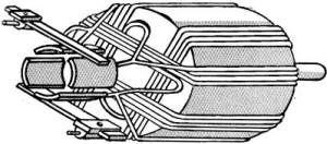
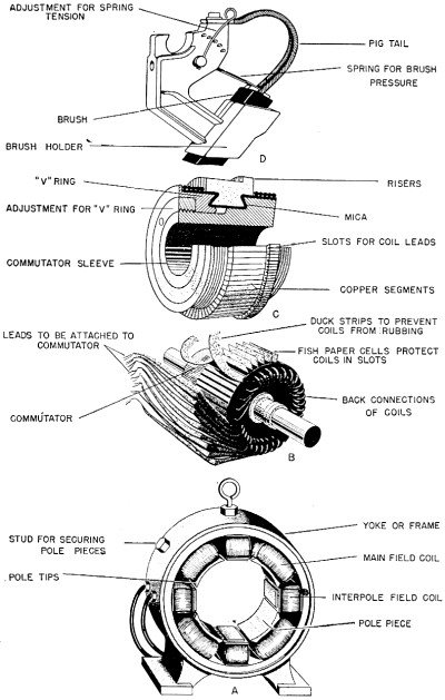
Figure 133. - Modern drum wound armature. Figure 133 shows a modern drum wound armature. notice the great number of coils and commutator segments to give this job a high and steady voltage. CALLING IT BY NAME "That thing," "jigger," "it," "thing-a-ma-bob," and "gadget," may be okay on the beach. But in your Navy you're supposed to know what you are talking about. In fact, you've got to be able to make OTHERS know what YOU'RE talking about. The parts of generators have accurate names - USE THEM. Figure 134 shows the four main parts of a generator-the FRAME, the ARMATURE, the COMMUTATOR, and the BRUSH RIGGING. Each part is labeled with its correct name. LEARN "EM"! You'll sound a lot more savvy on your job. ALTERNATORS - A-C GENERATORS It would be simple if alternators followed the generator pattern in their development-one -coil, two coils, many coils .. It would be nice and simple -BUT they just aren't built that way! Alternators have a special design that's MECHANICALLY OPPOSITE to the generator. Alternators ROTATE the FIELD and hold the ARMATURE STATIONARY.
It's perfectly true that alternators COULD be built by increasing the number
of turns of the coil and taking the a.c. off through slip rings. A coil of many
turns would step up the voltage to a usable value. And a very few alternators are
built this way. They work just like the d-c generator except that the commutator
is replaced by a set of slip rings.
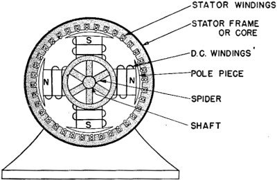
Figure 134. - Parts of a generator. Generating high voltages (as high as 25,000 volts) makes the use of slip rings impossible. Any voltage above 1,000 volts cannot be handled on slipping contacts - either commutator or slip rings - because of arcing. Even as much as 700 or 800 volts arcs dangerously. These arcs are like miniature bolts of lightning - jumping from brush to slip ring. Each arc digs a pit into the slip ring, soon wearing it out. When the voltage is in the thousands, arcs may jump from ring to ring, brush to brush, or brush to frame. It's obvious, then, that slip rings cannot be used to take high voltage a.c. off an alternator. ALTERNATORS-ROTOR AND STATOR To eliminate the dangers of arcing - and still generate high voltages - conductors are held stationary and the flux field is moved across them. The alternator does just that. The field poles are mounted on a shaft and rotated. This is the ROTOR of an alternator. The energizing current for the field poles - d.c. - must be fed into the rotor by slip rings. This energizing d.c. is at a low voltage, usually 110 or 220 volts, so it is safe to use slip rings. The armature is wound as a many-turn coil inside a slotted frame. This frame is stationary - it is called the STATOR of an alternator. Figure 135 is a cross section of a four pole alternator.
Figure 135. - Four pole alternator. It works this way - the rotor with its magnetic, field sweeps across the stator windings. As the lines of force are cut by the stator windings, a voltage is induced. Imagine the rotor of figure 135 turning. First the N pole flux cuts the left side of the stator. After one quarter of a revolution, the situation is reversed. The S pole flux cuts the left side, and the flux has reversed for all windings on the stator. The effect is that of reversing field direction. And, when field direction is reversed, so is the direction of induced EMF. Alternating current is the product.
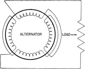
Figure 136. - Schematic of stator and load. The alternator builds up a strong voltage by having many turns on both rotor and stator. The multi-turn rotor produces a strong flux (NI). And the multi-turn stator is connected in series so that voltage adds. The combination of MANY conductors cutting a STRONG field generates high voltages. If you trace current through an alternator as you did through a Gramme ring, you will find the principles the same. Follow the current through figure 136. current enters the positive lead of the stator and travels through the windings. It picks UP the induced voltage, and leaves on the negative stator lead. Then it goes through the load, where it loses its voltage doing work, and returns to the stator to repeat the process. The fact that a.c. reverses direction periodically does not alter this process. Regardless of whether the current is positive or negative, it picks up voltage in the alternator and spends voltages in the load. MORE ON DESIGN Different electrical loads require the employment of generators of varying design.
An a-c load requires an alternator - a d-c load requires a generator. More specific
requirements are met by utilizing various connection patterns within the generator.
These more complex jobs are too advanced for this basic book. You have the PRINCIPLES
-you'll get the details in the book for YOUR rating.
Chapter 14 Quiz
|
|||||||||||||
 |
|||||||||||||
|
|||||||||||||


|
||||||||||||||||||||||||||||||||||||


