|
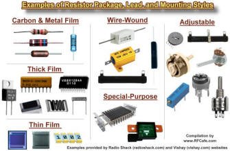
  Resistors are passive devices used in electronic
circuits to control the flow of current. An ideal resistor has no associated stray capacitance
or inductance, and therefore performs exactly the same in a direct current (DC) circuit
as it does in an alternating current (AC) circuit at any frequency. Resistors are passive devices used in electronic
circuits to control the flow of current. An ideal resistor has no associated stray capacitance
or inductance, and therefore performs exactly the same in a direct current (DC) circuit
as it does in an alternating current (AC) circuit at any frequency.

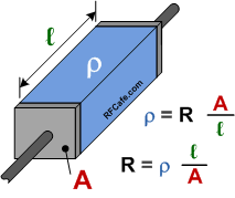
As an example of calculating a volume's resistance from its
bulk resistivity, consider the drawing to the left. Assume
12 AWG copper wire with a resistivity (from the table) of 1.72x10⁻⁶ Ω·cm,
a cross-sectional area (A) of 0.03309 cm2, and a length of 1 meter.
Per the given formula, its resistance is:
 , ,
which agrees well with typical specified Ω/km values published by wire manufacturers.
Alpha claims 1.59 Ω/1000' or 5.22 Ω/km.
|
Real-world resistors made of physical components exhibit more than just a pure resistance
when present in an AC circuit. A common circuit simulator model is shown to the left.
It includes the actual ideal resistor with a parallel capacitive component representing
inter-element (if present) mutual capacitance, and a series inductive component representing
lead and/or solder/bond pads that respond to
alternating current. SPICE-type simulators use this or an even more sophisticated model
to facilitate more accurate calculations over a wide range of frequencies.Equations
(formulas) for combining inductors in series and parallel are given below.
|


Total resistance of parallel-connected resistors is equal to the reciprocal of the
sum of the reciprocals of the individual resistances. Keep units constant.
|
|

 Total resistance of series-connected resistors is equal to the sum of the individual
resistances. Keep units constant.
|

As an example of calculating a volume's resistance from its
bulk resistivity, consider the drawing to the left. Assume
12 AWG copper wire with a resistivity (from the table) of 1.72x10⁻⁶ Ω·cm,
a cross-sectional area (A) of 0.03309 cm2, and a length of 1 meter.
Per the given formula, its resistance is:

|
|


 Resistors are passive devices used in electronic
circuits to control the flow of current. An ideal resistor has no associated stray capacitance
or inductance, and therefore performs exactly the same in a direct current (DC) circuit
as it does in an alternating current (AC) circuit at any frequency.


