|
|
|||||||||
| Software: RF Cascade Workbook | RF Symbols for Office | RF Symbols & Stencils for Visio | Espresso Workbook | ||||||||||
|
|||||||||||||||||||||||||||||||
   |
   |
||||||||||||||||||||||||||||||
|
Please Support RF Cafe by purchasing my ridiculously low-priced products, all of which I created. RF & Electronics Symbols for Visio RF & Electronics Symbols for Office RF & Electronics Stencils for Visio T-Shirts, Mugs, Cups, Ball Caps, Mouse Pads These Are Available for Free |
|||||||||||||||||||||||||||||||


Electrician's Mate 3 - Navy Training Courses
Chapter 4
NAVPERS 10548

Here is the "Electrician's Mate 3 - Navy Training Courses" (NAVPERS 10548) in its entirety (or will be eventually). It should provide one of the Internet's best resources for people seeking a basic electricity course - complete with examples worked out. See copyright. See Table of Contents.
¶ U.S. GOVERNMENT PRINTING OFFICE; 1949

CHAPTER 4
INDUCTION
ELECTRICITY FROM MAGNETISM
(* VERY IMPORTANT NOTE: Current flow here is defined as from negative to positive, which is
opposite of today's convention. Modern convention of positive-to-negative
current flow, with negative-to-positive electron flow requires a
"right-hand rule." See Right-Hand Rule page on RF Cafe).
To produce an electric current a source of emf is necessary. The oldest and simplest known source of emf is the piling up of a static charge; that is, generating electric charges by friction and storing up these charges in a condenser. While it is possible to build up static charges to potentials of many thousand volts, these charges cannot be used to provide power for electric motors and the like because very little energy is stored up in static charges. Hence, they possess no reserve or energy to keep the electric current flowing, and once the spark has jumped the gap the potential falls to almost zero and the flow of electrons practically stops.
As you learned in Basic Electricity, static charges can also be created continuously by a number of different electrostatic machines, but the rate of building is too slow to make these machines of practical value as a source of emf.
For many years, primary cells were the only practical source of emf, but these were able to produce only small currents-currents strong enough to power only low-current devices such as the telegraph and telephone. The electric motor, heating coils, and the hundred-and-one other heavy current-consuming devices common today were not possible since batteries could not furnish the required amount of current.
All the modern electrical machines had to wait until a cheaper, more efficient, and larger source of emf was found. This came about when the principle of INDUCED ELECTROMOTIVE FORCES, or ELECTROMAGNETIC INDUCTION was discovered by Michael Faraday in 1831. Though the development of this principle of obtaining electricity from magnetism came about little more than 100 years ago, such rapid progress has since been made in designing better and larger generators based on this principle that now millions of kilowatts of electric power are delivered by these machines daily to homes and industry. And in the Navy generators based on the induction principle discovered by Faraday have been so far developed that those used in battleships and carriers could supply whole cities of moderate size with all the electric power necessary to run their factories, operate their street cars, and meet all the other electric power requirements of the community.
The story of how a generator does this starts with the following illustration.

Figure 56. - An emf is produced when a conductor cuts a magnetic field.
In figure 56, a GALVANOMETER, an instrument that shows DIRECTION and AMOUNT of current, is connected to a conductor. When the CONDUCTOR is moved DOWNWARD, into the field between the poles of a magnet, the galvanometer NEEDLE is DEFLECTED, indicating a current to be flowing in the conductor. The current produced flows in such a direction that the needle is deflected from the center of the scale TO THE RIGHT, as the figure shows. When the CONDUCTOR is moved UPWARD, out of the field, the NEEDLE is DEFLECTED in the OPPOSITE DIRECTION, indicating that the current has been reversed. When the CONDUCTOR is held MOTIONLESS, NO DEFLECTION is present; but MOVING the conductor QUICKLY through the field produces a LARGE DEFLECTION of the needle, and a SLOW MOVEMENT produces a SMALL DEFLECTION.
Here is what you have observed:
A downward movement of the conductor causes a deflection of the galvanometer
in one direction.
An upward movement causes a deflection in the opposite direction.
The faster the movement, the greater the deflection. No movement, no deflection.
Figure 57. - Direction of induced emf depends on direction of cutting a magnetic field.
You therefore conclude, as Faraday did when he discovered this phenomenon, that: MOVING A CONDUCTOR ACROSS A MAGNETIC FIELD GENERATES AN EMF which produces a current in the conductor; THE FASTER THE CONDUCTOR MOVES, THE GREATER THE EMF PRODUCED and therefore the greater the current; and REVERSING THE DIRECTION OF MOVEMENT OF THE CONDUCTOR REVERSES THE EMF and therefore also reverses the current.
INDUCTION
The phenomenon of generating an emf and thus causing a current to flow in a conductor when it cuts across a magnetic field, as illustrated in figures 56 and 57, is called INDUCTION. Although in these illustrations the conductor moved and the field stood still, a VOLTAGE CAN ALSO BE INDUCED BY MOVING THE FIELD AND HOLDING THE CONDUCTOR STATIONARY. Thus, INDUCTION will take place whenever you have a MAGNETIC FIELD, a CONDUCTOR and a RELATIVE MOVEMENT exists between the two.
WHICH WAY AND HOW MUCH
There are two points about the phenomenon of induction that are of considerable importance to an electrician's mate. The first is, IN WHICH DIRECTION will the current flow? And the second is, HOW MUCH current will flow? The first can be answered using a simple hand rule, but the second requires the use of delicate measuring instruments.
HAND RULE FOR GENERATORS
The direction of the induced current depends on the direction of the magnetic field, and the direction of movement of the conductor relative to the field. Notice that this makes THREE "directions" involved in determining the direction of an induced current. They are- The direction in which the CONDUCTOR is MOVING relative to the flux.
The direction of the flux FIELD. The direction of the INDUCED EMF. All three "directions" are inter-dependent, and are summed up in the GENERATOR HAND RULE. It states- Place the thumb, first, and middle fingers of the left hand all at right angles to each other as in figure 58. Then the FIRST FINGER points in the FLUX direction, the THUMB points in the direction of the MOTION of the conductor, and the MIDDLE FINGER points in the direction of the INDUCED EMF.
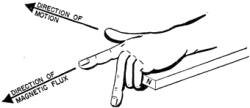
Figure 58. - The generator hand rule.
Figure 59 illustrates three examples of changing one of the directions. Note that the direction of emf changes every time either the direction of conductor motion, or direction of the magnetic field changes.
The generator hand rule will tell you the third "direction" anytime you know the other two. Sometimes it will be difficult to get your finger lined up with the known directions but just remember that it makes no difference whether you face the conductor, stand to one side of the conductor, or turn your back to the conductor. As long as your thumb points in the direction of motion, your first finger in the direction of the flux, then your middle finger must point in the direction of the induced emf. Stand on your head if you must-but get those fingers lined up! It might help you to construct a drawing like figure 60. Draw a circle for the cross-section of the conductor. Then run arrows out in the direction of the flux and the motion. You can apply :he generator hand rule directly to the diagram. YOUR middle finger tells you whether a dot (.) or a cross (+) goes ill the cross-section of the wire. 135. DIRECTION OF FLUX DIRECTION OF FLUX (C)

Figure 59. - Generator hand rule, examples.
The left hand rule is important because you will use it many times in your work on generators to determine the direction of the current. It can also be used to determine the polarity of a generator field if you know the direction of the current and direction of rotation of the armature.
Figure 60. - Model for the generator hand rule.
STRENGTH OF INDUCED EMF'S
You learned in an earlier paragraph that the faster the conductor moves across a magnetic field, the greater the induced emf. In moving across a magnetic field the conductor is cutting lines of force. So another way to say this is:
THE MORE FLUX LINES A CONDUCTOR CUTS EACH SECOND THE GREATER IS THE INDUCED EMF.
It has been calculated that 100,000,000 LINES of flux must be CUT PER SECOND to PRODUCE ONE VOLT. Then 200,000,000 lines cut per second would produce 2 volts, etc. This is a lot of flux to cut in one second, so to make generators which produce appreciable voltages they must have powerful magnetic fields. The fields produced by permanent magnets are relatively weak, but with electromagnets enormously powerful fields can be produced. That is why the field magnets of all generators are electromagnets.
METHODS OF INCREASING INDUCED EMF'S
This principle, THE NUMBER OF FLUX LINES CUT PER SECOND, is the key to all the possible methods for increasing the voltage output of a generator. There are three: 1) cut ;he lines faster, by increasing the speed of movement of the conductor; 2) cut more lines with the same conductor, which means increasing the strength of the magnetic field; and 3) cut the lines with more than one conductor, which means making the conductor into a coil so that the field is cut by many lengths of the same conductor, instead of by a single length.
Method (1) is accomplished by increasing the speed of rotation of the generator. This explains the increased 70ltage output of an automobile or motor-launch generator when the engine is raced.
Method (2) is accomplished by increasing the ampere-turns of the electromagnet producing the field. This can be done either by increasing the field current, or by increasing the number of turns of the magnet coil.
Method (3) works because when a conductor is formed into a coil, each turn is in series with the other turns. There£ore, the voltage generated in each turn is added to the voltages generated in the other. Thus, suppose one conductor cutting a field produces 10 volts. This same conductor, coiled into 5 turns, and cutting the same field, will produce 50 volts.
MUTUAL INDUCTION
"Mutual" means that something is shared. MUTUAL INDUCTION means that two circuits share the energy of one. Strictly speaking, it means an electrical phenomenon in which, energy is transferred from one circuit to another. How it is done is shown in figure 61. Coil A is the PRIMARY circuit and gets its energy from the battery. When the switch is closed the current starts to flow and a magnetic field expands out of coil A. Coil A thus changes the ELECTRICAL energy of the battery into the MAGNETIC energy of a magnetic field. When the field of coil A is expanding it cuts across coil B (the SECONDARY circuit), inducing an emf in coil B. The galvanometer in circuit B is then deflected, indicating the current produced by the induced emf.
Here is an interesting fact - the induced voltage MIGHT have resulted from moving coil B through the flux of coil A. But the voltage was induced WITHOUT moving coil B. When the switch to A was open, A had no current and no field. But as soon as the switch was closed, current surged through the coil and a field blossomed out. This expanding field "moved" across the wires of coil B-thus lines of force were cut and a voltage was induced, WITHOUT MOVING COIL B.
In a small fraction of a second the field expands to its maximum strength and remains constant as long as the full current flows. "Moving" of flux lines across coil B stops and induction ceases-as shown by galvanometer returning to zero. If the switch is opened, the field collapses back to the wires of coil A. Again the changing flux "moves" across the wires of coil B, but in the opposite direction. The galvanometer needle now deflects, but in the opposite direction, indicating that a voltage has again been induced, but in the reverse direction. The important point for you to see here is that INDUCTION OCCURS ONLY WHEN A FIELD IS CHANGING - either building up or collapsing, and that a CHANGING FIELD PRODUCES INDUCED EMF'S EXACTLY AS A FIELD MOVING ACROSS A CONDUCTOR. This principle of generating induced voltage by holding the coils steady and forcing the field to change is used in a vast number of elec6cal devices. The spark coil in an automobile and the transformer are the most common.
Figure 61. - Mutual induction circuits.
You can always spot a MUTUAL INDUCTION set-up by its TWO circuits. One circuit - the primary - gets its energy from a voltage source (generator or battery) and the other circuit - the secondary - gets its energy by induction from the field of the primary.
In summary, there are then two methods of generating INDUCED emf's:
When lines of force are cut by a conductor, due to movement of the field or the conductor.
This is the principle underlying all generators.
When the current in a primary circuit changes, and its flux lines cut across the conductors
of the secondary. This principle underlies all transformers, induction coils, etc.
LENZ'S LAW
The principle that a conductor carrying a current is surrounded by a magnetic field holds true for currents resulting from induced emf's as well as for currents from any other source. To illustrate this, look at the four drawings in DOWNWARD PUSH N as A N figure 62. The first diagram, A, shows a conductor at rest in a stationary magnetic field. Being stationary, the conductor has no induced emf and no current. The second diagram, B, shows the conductor being pushed downward. Note that two items have been added-the downward push and the resulting induced current in the conductor. Since a magnetic field surrounds every conductor carrying current, the conductor will have a field of its own due to the induced current, and the generator hand rule tells you that this field will be in a counter-clockwise direction, as shown in the third diagram, C. There are now TWO fields surrounding the conductor-the one from the MAGNET and the one from the induced CURRENT in the conductor. The first is a straight line field travelling from the North pole to the South pole. The second is a circular field surrounding the conductor.
Figure 62. - Lenz's law.
Because magnetic lines never cross, the lines of these two fields must either CROWD TOGETHER producing a STRONG resultant field, or they must CANCEL, producing a WEAK resultant field. A of figure 63 shows what happens ABOVE the wire. The two magnetic fields meet head-on and CANCEL each other. The cancellation of flux lines results in a WEAK field ABOVE the conductor.
Figure 63. - Lenz's law-action between conductor and magnetic fields.
B of figure 63 shows that BELOW the wire the two magnetic fields are in the same direction, so their fluxes ADD. This addition of flux lines results in a STRONG field BELOW the conductor.
Thus as a result of the induced current, the magnet field is distorted by the field around the conductor, resulting in a weak field above and a strong field below the conductor. Now remember that flux lines tend to push each other apart.
Therefore, as you can see in figure 62D, the flux LINES BELOW the conductor, pushing each other apart, tend to PUSH the conductor UP, while the LINES ABOVE the conductor tend to PUSH it DOWN. But there are more flux lines below the conductor, so the upward push is greater, and the conductor has magnetic force tending to move it up. All these conditions are summed up in D of figure 62. Better review them. Refering to figures 62 and 63, you observe -
The DISTORTED FIELD resulting from the combination of the straight field of the poles
and the circular field of the induced current in the conductor.
The DOWNWARD FORCE applied by a push on the conductor.
The UPWARD FORCE which results from the distorted field.
These facts tell you that whenever you apply a push to shove a conductor across a magnetic field, there is induced a current which sets up a field that tries to move the conductor back against the push. This is Lenz's law: IN ALL CASES OF ELECTROMAGNETIC INDUCTION, THE DIRECTION OF THE INDUCED EMF IS SUCH THAT THE MAGNETIC FIELD SET UP BY THE RESULTING CURRENT TENDS TO STOP THE MOTION WHICH IS PRODUCING THE EMF.
LENZ'S LAW AND THE OPERATION OF GENERATORS
Let's look into this action a little further. Suppose you try to push a conductor DOWNWARD through a magnetic field. Immediately the induced current sets up a field that tries to push the conductor UPWARD (Fig. 62D). The force YOU use in the DOWNWARD push is bucked by the magnetic UPWARD push. If you push harder, the conductor goes faster, cuts magnetic lines faster, and so has a higher induced emf. But this only produces more induced current and a stronger conductor field. Consequently, a stronger UPWARD force is automatically produced to buck the stronger DOWNWARD force.
So, if you push a conductor faster across a magnetic field t0 produce more electrical output, you have to push harder on the conductor. Practically this means that, to get more electrical output from a generator, you have to use more power to drive the generator. For example, if the generator is driven by a steam engine, you must increase the steam flow to increase the generator output.
Here's another example. Have you ever heard a motor-driven welding generator? When the welding arc is struck the driving motor whines and labors. Lenz's law is working. The arc increased the generator's current output and the driving motor is working against the increased opposing force which was set up by this increased current. The motor must increase its input to balance the increased output for the arc.
SELF INDUCTION
There are only three items required to generate an induced voltage-a conductor, a magnetic field, and moving or changing flux lines of this field cutting across the conductor. These three items give you LINES OF FORCE CUT BY A CONDUCTOR. Look at figure 64. Are these three items present in this circuit?
Conductors? - the coil has plenty of them.
Magnetic field? - the coil sets it up whenever current flows.
Flux lines cutting the conductor? - occurs only when the field is changing.
Figure 64. - Self-induction circuit.
To make the field change, all you have to do is open and close the switch. This kind of induction is called SELF-INDUCTION, and here is how it works: At the instant the switch is closed the current starts and magnetic lines expand from the center of each conductor. As these lines blossom outward, they cut across the other conductors of the coil. An emf is induced in each conductor cut by the flux.
Figure 65 shows an enlargement of only two turns of the coil in figure 64. Flux is pictured blossoming out from one of the turns. Notice how t
hese lines cut the next turn.
Figure 65. - Self-induction in one turn.
Figure 66. - Self-induction fields around conductors.
Now, applying the generator hand rule, determine the direction of the induced voltage in the second turn. It's easier to use the rule on a cross-section of the coil as in figure 66. Flux direction is down (first finger). Motion is to the right thumb). (Attention - the flux is moving across the. conductor to the left - the effect is the same as though the conductor were moving to the right.) Induced voltage (middle finger) is in a direction into the paper. But the battery voltage is producing current flow out. Hence that is exactly what happens. THE INDUCED VOLTAGE OPPOSES THE FLOW OF CURRENT.
What happens when the switch is opened? The field collapses and cuts across the conductor in the opposite direction. Because the direction of motion has reversed, the induced emf is now IN. Thus, IN A COLLAPSING FIELD, THE INDUCED EMF AIDS THE FLOW OF CURRENT.
These are the characteristics of self-induction -
Any coil will INDUCE a VOLTAGE in itself WHENEVER its CURRENT value CHANGES.
When the CURRENT is INCREASING (field expanding), the INDUCED EMF OPPOSES
CURRENT FLOW.
When the CURRENT IS DECREASING (field contracting), the INDUCED EMF AIDS
the CURRENT flow.
This is in effect, just another case of Lenz's law. Only in place of the force moving the conductor you have the applied voltage from the battery, and in place of the bucking force you have the self-induced voltage. Hence for self-induction, Lenz's law states: the induced voltage OPPOSES the applied voltage when the current is INCREASING and AIDS the applied voltage when the current is DECREASING. Or, in self-induction the INDUCED VOLTAGE OPPOSES ANY CHANGES IN THE CURRENT value.
SELF-INDUCTION - THE HARM IN IT
The voltage of self induction can be very troublesome. Imagine that you are operating the switch controlling the field coils on a large motor. These coils have thousands of turns. When the switch is closed, the voltage of self induction does little damage. It opposes the increase of current flow for an instant (perhaps 0.1 second), but as soon as the field is built up and stationary, the induced voltage ceases. On the other hand, when the switch is opened, the field rapidly contracts. The induced voltage on collapse may be hundreds of times as strong as the applied voltage. This tremendous induced voltage drives current across the opening switch terminals in the form of an arc - it CAN burn both the operator and the switch very badly. All switches subject -- high induced voltages are protected by discharge rheostat to absorb and dissipate the induced voltage, which might otherwise cause dangerous arcs.
SELF-INDUCTION - THE GOOD IN IT
The voltage of self-induction can also be very useful. Imagine that you close the switch to energize the sucking coil of a relay. The instant the switch is closed the current starts to rush in, but this produces a large bucking voltage of self-induction which largely cancels the applied voltage, E. Very little voltage is therefore left to force current through the circuit, and so only a small current flows through the relay a immediately after the switch is closed.
As the voltage of self-induction dies down, the voltage applied to the coil circuit comes up to the full applied voltage, E, and the current builds up GRADUALLY to the full value given by I=E/R. Since the sucking coil will not pull in the iron core until nearly the full I=E/R current is flowing, there is a TIME DELAY between the closing of the circuit of the relay coil and the pull-in of the relay core. The greater the coil's inductance, the greater this time delay.
Time delays are necessary between the opening and closing of different circuits for motor starting, for motor stopping, for the safe operation of much other electrical equipment aboard ship. You will therefore run across time delay relays in nearly all the electrical equipment you work on. Remember, the time delay depends on the inductance of the relay coil; so if you have to replace the coil of one of these
BE SURE THE REPLACEMENT COIL HAS THE RIGHT INDUCTANCE to produce the required time delay.
NONINDUCTIVE COILS
Some electrical circuits require NONINDUCTIVE coils for operation. You say how come? How is it possible to have a noninductive coil since all conductors carrying a current are surrounded by magnetic fields? Look at figure 67. The wire used to wind the coil is DOUBLED BACK, as illustrated in diagram A, so the starting end of the conductor is next to the finishing end. The current flows from left to right in the upper wire but returns in the OPPOSITE direction in the lower wire, therefore the MAGNETIC FIELDS in the two wires will be OPPOSITE and CANCEL each other.
Figure 67. - Noninductive coil.
When the DOUBLED conductor is wound about a core as illustrated in figure 67B, the magnetic fields cancel each other, resulting in a noninductive coil.
EDDY CURRENTS
A solid piece of metal usually is not thought of as a conductor in the same sense as the word "conductor" is used with electrical circuits, but if a solid piece of metal moves through a magnetic field it too will have an emf induced in it.
Figure 68. - Eddy currents in a disk.
In figure 68 the edge of a metal disk is placed between the poles of a horseshoe magnet. As long as the disk is motionless, emf will be induced, but any motion by either the magnet he disk will result in flux lines being cut by a conductor so will cause a small current to circulate within the metal. Since these currents have random movements and follow irregular paths they are called EDDY CURRENTS.
Eddy currents obey all the usual laws of induction. The most evident is the OPPOSITION TO MOVEMENT according to Lentz's law. As an example, if the disc in figure 68 is being continuously rotated, the eddy currents will cause a DRAG d tend to slow down the rotation of the disc.
Large, thick pieces of metals have stronger eddy currents than thin, small sections, because the larger cross sections offer less resistance to the induced emf. Electrical devices like generators and motors where large quantities of iron rotate in magnetic fields have their iron cores made of many small thin sections or LAMINATIONS bolted together, rather than one large solid casting. The laminations do not PREVENT eddy currents, they merely REDUCE them, because they increase the resistance of the eddy current path. The effect of lamination is illustrated in figure 69. Notice the difference in the size of eddy currents in the two diagrams.
Figure 69. - Effect of laminations on eddy currents.
Eddy currents, like all other currents, produce heating. Heating of the iron cores of electrical motors and generators only wastes energy and damages the insulation of the winding. It is therefore very important that the cores of electrical machines be laminated, to reduce the eddy currents and therefore their heating effects.
Some electrical instruments such as sensitive voltmeters and ammeters use solid iron cores to INCREASE the effect of eddy currents. This is done to produce a DAMPING EFFECT or drag, that causes the needle to come to rest QUICKLY after energy has been applied to the meter. Without DAMPING action, the meter needle would swing back forth for many minutes thus making the task of obtain meter readings slow and tedious.
Chapter 4 Quiz

Copyright: 1996 - 2026 |
About RF Cafe RF Cafe began life in 1996 as "RF Tools" in an AOL screen name web space totaling 2 MB. Its primary purpose was to provide me with ready access to commonly needed formulas and reference material while performing my work as an RF system and circuit design engineer. The World Wide Web (Internet) was largely an unknown entity at the time and bandwidth was a scarce commodity. Dial-up modems blazed along at 14.4 kbps while tying up your telephone line, and a lady's voice announced "You've Got Mail" when a new message arrived... |
Copyright 1996 - 2026 All trademarks, copyrights, patents, and other rights of ownership to images
and text used on the RF Cafe website are hereby acknowledge My Hobby Website: My Daughter's Website: |
