|
Here is the "Electrician's Mate 3 - Navy Training Courses"
(NAVPERS 10548) in its entirety (or will be eventually). It should provide one of
the Internet's best resources for people seeking a basic electricity course - complete
with examples worked out. See
copyright.
See Table of Contents.
¶ U.S. GOVERNMENT PRINTING OFFICE;
1949

CHAPTER 3
ELECTROMAGNETISM AND MAGNETIC CIRCUITS
OERSTED'S DISCOVERY
NOTICE: This page has not been proofed yet!
(* VERY IMPORTANT NOTE:
Current flow here is defined as from negative to positive, which is
opposite of today's convention. Modern convention of positive-to-negative
current flow, with negative-to-positive electron flow requires a
"right-hand rule." See
Right-Hand Rule
page on RF Cafe).
In 1819, Hans Christian Oersted, a Danish scientist, made one of the most important single discoveries in the
field of electricity. While experimenting he accidentally brought a small compass near a wire carrying an electric
current and noted that the needle no longer assumed its usual north-south direction, but aligned itself at right
angles to the wire. By this observation he had discovered the principle of electromagnetism-namely, that A
MAGNETIC FIELD ALWAYS SURROUNDS A CONDUCTOR CARRYING A CURRENT. While he probably didn't realize its importance,
Oersteds had discovered the key to the vast fields of commercial electricity. MAGNETIC FIELD AROUND A CURRENT-CARRYING CONDUCTOR*
You learned in the chapter on magnetism that whenever electrons move a magnetic field is created at right
angles to their direction of motion. Therefore, whenever a current flows, a magnetic field always exists around
it. If the conductor in which the current flows is a straight wire, the field takes the form of concentric circles
or rings of magnetic force around the wire, as shown in figure 42. You can check this experimentally with a small
pocket compass. Since a compass needle always aligns itself parallel to magnetic lines of force, the needle also
will be at right angles to a current-carrying conductor. You can perform this experiment with dry cell, a piece of
wire, and a compass as shown in figure 43.
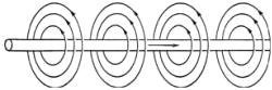
Figure 42. - Magnetic field about a conductor carrying a current.*

Figure 43. - Experiment to detect the field about a current-carrying conductor.*
If the direction of current in the conductor is reversed, the compass needle will reverse, indicating that the
magnetic lines circling the conductor are in the opposite direction.
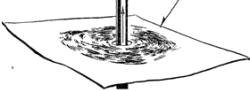
Figure 44. - Experiment to show circular nature of magnetic field
around a
current-carrying conductor.
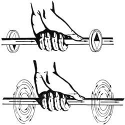
Figure 45. - Left hand rule for a conductor.*
as in figure 44, a current is sent through a conductor ._~unded by a cardboard on which iron filings have been
added, the filings will assume a circular pattern. This clearly the circular nature of the magnetic field around
conductor carrying current. LEFT HAND RULE FOR A CURRENT-CARRYING CONDUCTOR*
Here is an important rule .. You have heard it before, but review it again. IF A. CURRENT-CARRYING CONDUCTOR
IS GRASPED IN THE LEFT HAND WITH THE THUMB POINTING IN THE DIRECTION OF ELECTRON FLOW (NEGATIVE TO POSITIVE), THE
FINGERS WILL POINT IN THE DIRECTION OF THE MAGNETIC LINES OF FLUX. :figure 45 shows the application of the left
hand rule. Notice
Years ago, scientists named the COPPER terminal of a primary cell the. POSITIVE terminal and the ZINC the
NEGATIVE, and said the direction of current flow was from POSITIVE to NEGATIVE. Modern experiments have shown that
a current of electricity is really a flow of electrons, and the direction of flow is from NEGATIVE to POSITIVE.
Nevertheless the old theory is still used in many electrical textbooks and in some Navy manuals. If you run across
the old theory, don't let it confuse you. In those cases where you find that current is traced from positive to
negative, simply use the OPPOSITE HAND from the one used in this book. Your answer will then be correct.
Throughout this book all explanations are based on the present-day idea-that current flow is
a flow of electrons, from NEGATIVE to POSITIVE*. LEFT HAND RULE TO FIND THE DIRECTION OF CURRENT*
By using a pocket compass and the left hand rule you can determine the direction in which the current is
flowing in a conductor. Grasp the conductor in the left hand with the FINGERS pointing in the same DIRECTION as
the NORTH POLE of the compass; the THUMB will then point IN the DIRECTION in which the CURRENT is flowing. In
electrical diagrams arrows are usually added to mark the direction of current flow. This works well along the
length of the wire, but where cross-sections of wire are shown, a special view of the arrow must be used. Look at
figure 46.

Figure 46. - Current flowing in and out of a conductor.*
The left drawing shows an arrow coming out of the wire. If you cut this wire, and look at it from the end, you
will see the head of the arrow coming out of the wire. So a DOT (.) is the symbol used to indicate the current
coming OUT of a wire. When the current is flowing into the wire, the cross-section shows the feathered tail of the
arrow. So a CROSS (+) representing the tail of the arrow is used to indicate a current going INTO a "ire. Figure
47 shows cross-section views of two conductors. Both directions of current flow are indicated. Use the left-hand
rule to check these labels. Your thumb should point 54 O
53. TIP out of the page for the left-hand drawing, and down into the page for the right-hand drawing. THE
MAGNETIC FIELD AROUND A SINGLE CONDUCTOR The greater the current in the conductor, the stronger will be the
magnetic field around it and the further out this field will extend from the conductor. You can see why this is so
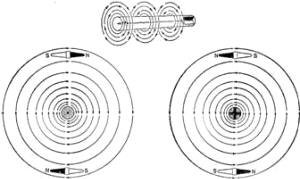
Figure 47. - Cross-sectional view of a magnetic field around a conductor.*

Figure 48. - Repulsion between parallel conductors.*
from the following explanation of how the field is built up. The lines of force are assumed to start as a dot
in the center of the conductor. When the current starts to flow, these circular lines of force expand from this
dot. As the current increases new lines are formed. Since the magnetic lines of force flowing in the same
direction tend to push each other apart, the new lines of force cause those already formed to expand outward.
Therefore the greater the current the farther the field extends outward. The field surrounding a conductor
carrying a large current may extend outward several feet. When the current ceases to flow the magnetic field
disappears, as if the lines of force had collapsed back into the center of the conductor. MAGNETIC FIELDS ABOUT PARALLEL CURRENT-CARRYING CONDUCTORS
Suppose you have two long conductors arranged parallel and close together. If the two conductors are carrying
CURRENTS in OPPOSITE directions the magnetic fields around the wires will be as shown in figure 48, with the lines
of force of both magnetic fields flowing in the same direction, and the two fields add in the space between both
wires. Since lines of force traveling in the same direction tend to push each other apart, this will result in a
REPULSION BETWEEN THE TWO CONDUCTORS. Figure 49 shows two parallel conductors with CURRENT flowing IN the SAME
DIRECTION in each conductor. In the space between the two conductors the lines of force for both conductors are
now in opposite directions, and cancel each other. But the lines of force surrounding both conductors remain.
Since these lines of force act like elastic bands trying to shorten themselves, they tend to PULL THE CONDUCTORS
TOGETHER. The two preceding paragraphs can be summarized into the following rule: Conductors carrying currents in
the SAME direction ATTRACT one another, and conductors carrying currents in OPPOSITE directions REPEL one another.
This rule is sometimes very impressively demonstrated in modern, large-capacity power systems. In some cases
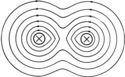
Figure 49. - Attraction between conductors.*
bus bars have been wrenched from their clamps, and even transformers coils have been pulled out of place and
the transformers wrecked, by the magnetic forces produced by the extremely large currents which result from a
short circuit. MAGNETIC FIELD ABOUT A CURRENT-CARRYING LOOP From your study of magnetism you learned that a
magnet's lines of force travel in a closed loop, from north to south
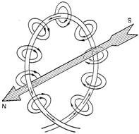
Figure 50. - Magnetic field about a loop. outside the magnet,
and from south to
north inside.*
If a current-carrying conductor is formed into a loop then, as shown in figure 50, all the lines of force are
entering on one side of the loop and leaving on the other side. Thus with a current of electricity you have
produced a magnet (called an ELECTROMAGNET) with a definite north and south pole. Figure 51 shows an interesting
comparison between the magnetic field set up around a current-carrying loop of wire
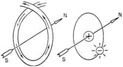
Figure 51. - Comparison of a current-carrying loop and an atom.*
and the field set up by an electron rotating around the nucleus of an atom. The electron in its motion about
the nucleus creates a magnetic field in much the same way as the electrons circulating through the wire. COILS
When it is desired to produce a magnetic field by an electric current, the wire is formed into a coil instead
of a single loop. A conductor wound as a coil (helix) is called a SOLENOID. The solenoid may thus be considered as
consisting of a large number of single loops, all connected in series and placed close together as in figure 52.
The solenoid may have a winding of one or several layers. Figure 52 shows the magnetic field set up about a
current-carrying coil. Since the current flows in the same direction in each turn, you have the effect of parallel
conductors carrying currents in the same direction. In the spaces between turns the flux lines are opposite and
cancel, so if the turns are close together only a small amount of flux passes through between the turns, most of
the flux being forced to pass around all the turns and through the center
58
of the coil, concentrating the flux at the center. As in a permanent magnet, the end from which the flux lines
leave the coil is called the NORTH pole. LEFT HAND RULE FOR A CURRENT-CARRYING COIL There is a left hand rule for
coils similar to the one for conductors. This rule is: Grasp the coil in the left hand with the FINGERS pointing
in the direction of the ELECTRON
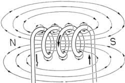
Figure 52. - Magnetic field surrounding a solenoid.*
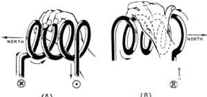
Figure 53. - Left hand rule for coils.*
the THUMB will then point in the direction of the NORTH pole end of the coil. Figure 53 illustrates an
application of this rule. SOLENOID AND PLUNGER
You have learned by experience that a piece of soft iron is attracted to a permanent magnet. Now if you place
the soft iron bar in the field of an electromagnet produced by current-carrying coil, you will get similar
results. As shown in figure 54, the lines of force will flow through the soft iron and magnetize it temporarily.
Since the lines of force tend to shorten themselves, the iron bar is pulled toward the coil. If the iron bar is
free to move, it will be drawn into the coil to a position near the center, where the pull is greatest. Such a
solenoid with a moving iron plunger is sometimes called a SUCKING COIL, and the plunger is called a
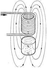
Figure 54.- Solenoid with an iron core.*
The solenoid-and-plunger principle is employed extensively aboard ships to operate the feeding mechanism of
carbon arc searchlights; to open circuit-breakers automatically when the load current becomes excessive; to close
switches for motorboat starting; to fire guns; and to operate flood valves, magnetic brakes, and many other
devices.
ELECTROMAGNETS
Strictly speaking, a single loop of wire or any coil carrying current is an electromagnet. However, it is
general practice to speak of a coil of wire having a 80ft iron core as an ELECTROMAGNET. The soft iron core offers
less opposition to the flow of magnetic lines than does air. Therefore, a coil having an iron core and surrounded
by an iron jacket will have a much stronger magnetic field than the same coil without an iron core. Generators;
motors, relays, electric bells, buzzers, dynamic loudspeaker fields, are a few of the many machines that use
electromagnets. MAGNETIC CIRCUITS
A MAGNETIC CIRCUIT is the COMPLETE PATH TAKEN BY MAGNETIC LINES OF FORCE in flowing out from their starting
point, the north pole, through the adjoining magnetic conductor or nonmagnetic materials, then into the south pole
and back through the magnet to the north pole. In figure 55 the path of the broken lines (indicating lines of
flux) running through one pole, around the yoke to the other pole, then through the armature and finally back to
the starting point, is an example of a magnetic circuit.

Figure 55. - Magnetic circuit in a bipolar generator*
In studying electric circuits you learned that the basic factors of every complete circuit are: voltage,
resistance of the conductor and the current. Magnetic circuits have similar factors; MAGNETOMOTIVE FORCE,
RELUCTANCE, PERMEABILITY, and FLUX. MAGNETO MOTIVE FORCE
MAGNETOMOTIVE FORCE (MMF) is similar to electromotive force, in that it causes the flux to flow in the
magnetic circuit. In electromagnets, the MMF comes from the current flowing through the coil. '.':he NUMBER OF
TURNS of wire in a coil MULTIPLIED BY the NUMBER OF AMPERES flowing expresses the MMF of the coil in AMPERE-TURNS.
You can increase the" magnetic pull" of a solenoid by increasing the number of turns of wire in the coil, by
increasing the number of amperes flowing through it, or both. One AMPERE-TURN of MMF is equivalent to a SINGLE
LOOP of wire CARRYING a current of ONE AMPERE. The UNIT of magnetomotive force is the GILBERT. RELUCTANCE
The RELUCTANCE in a magnetic circuit is similar to the resistance in electrical circuits. It is the opposition
offered to the flow of magnetic flux. Air offers greater reluctance to the flow of magnetic lines than any other
common form of matter and soft iron offers the least. Various kinds of iron and steel offer varying degrees of
reluctance and each has its use in the design of electrical machinery and apparatus. The unit of reluctance has
not been given a name but it is referred to by the symbol CGS and is equivalent to the reluctance offered to the
flow of magnetic lines of force by a cubic centimeter of air. PERMEABILITY
PERMEABILITY is the RATIO OF the ABILITY of any material to conduct magnetic lines of force to the ability of
a mass of air of the same shape and size TO CONDUCT FLUX. Air is considered the standard unit and is given the
value of 1.
As an example, if the permeability of iron is 50, the ratio of flux conductivity between iron and air is 50 to
1, and a cubic inch of iron will conduct 50 times as many lines of force as a cubic inch of air. Permeability of
matter is of utmost importance to the designer of electrical machinery but as Electrician's Mate 3d class, it is
only necessary to -understand the ratio that the word represents. FLUX
FLUX corresponds to the current in an electric circuit. Flux may be considered as the NUMBER OF MAGNETIC LINES
OF FORCE that flow in a magnetic circuit. The UNIT of flux is the MAXWELL, but this term is seldom used and the
amount of flux in a magnetic circuit is usually referred to as so many lines of force, or LINES OF MAGNETIC
INDUCTION. OHM'S LAW FOR MAGNETIC CIRCUITS
There is a law for the flux in a magnetic circuit which is similar to Ohm's law for the current in an electric
circuit. It states: FLUX IS DIRECTLY PROPORTIONAL TO THE MAGNETOMOTIVE FORCE AND INVERSELY PROPORTIONAL TO THE
RELUCTANCE OF THE MAGNETIC CIRCUIT. Thus; MAGNETIC CIRCUIT ELECTRICAL CIRCUIT FI Magnetomotive force C t
Electromotive force
FLUX DENSITY is expressed as the number of lines of force round in a unit of cross section area, such as
square inch or square centimeter. The UNIT of flux density is the GAUSS. SATURATION
In the electric circuit, the greater the EMF the more current :lows in the circuit. But the Ohm's law for a
magnetic circuit holds good only up to a certain maximum flux density. When this flux density is reached, the
application of any additional magnetomotive force will not produce any appreciable increase in flux. The material
is then said to be 8.TURATED. The flux density at which saturation is reached is different for different
materials. Saturation is important in the design of electrical machinery, because it is the main factor in
determining how large an iron core must be used for a certain size motor, generator, or transformer. RETENTIVITY AND RESIDUAL MAGNETISM
RETENTIVITY is the property of some magnetic substances to retain part of their magnetism after the
magnetomotive force has been removed. The flux retained is called the RESIDUAL magnetism. The property of
retentivity is desirable in some d-c electrical generators, as explained in Chapter 6. In a-c devices retentivity
is objectionable because a magnetomotive force must be developed to destroy the residual magnetism. Not only is
energy used up in creating this magnetomotive force, but this energy is used up in heating the magnetic material,
and this heat may injure the insulation of the electromagnet winding. All iron and steel do not have retentivity
in equal amounts. It is highest in hard steel. MAGNETIC LOSSES
Many high sounding names are connected with magnetic losses but only a brief explanation of these losses is
necessary at this time. Magnetic losses are the result mainly of the friction between the atoms or molecules when
they are forced into alignment by the magnetic lines of force. This friction is called HYSTERESIS, and overcoming
it actually produces heat in the magnetic material, an evidence of energy loss. Vibration and chattering of the
magnetic material are often signs of a magnetic loss. Beyond this explanation do not worry about magnetic losses
as they are accounted for in the design of the equipment. MAGNETIC ADJUSTMENTS
Unlike electrical circuits, magnetic circuits are designed in most cases so as not to required any adjustment,
and re-main as installed. Their presence, use, and basic theory should be understood, but do not worry about
altering or adjusting them. \Vhen it is necessary to make repairs or adjustments consult the manufacturer's
instructions for the equipment and be guided by experienced electrician's mates on your ship.
Chapter 3 Quiz
(click
here)
|


