|
|||||||||||||
 |
|||||||||||||
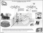
Drone-Based Field Measurement System™ (dB-FMS)™ |
|||||||||||||
|
The concept came to me while reading a column in QST magazine discussing the use of the EZNEC antenna radiation pattern prediction software. As you know unless an antenna is situated in a perfect, unobstructed environment like in the middle of a desert with a perfectly uniform ground or on a space-based platform, physical obstacles and variations in surface conductivity can significantly alter the 3-dimensional field distribution. Columnist Joel Hallas (W1ZR) is a master at EZNEC and is routinely called upon to model antenna systems for people. As important as length and orientation of antenna elements are, the ground plane configuration can have a profound impact on the radiation pattern, particularly when the antenna is less than a wavelength above ground. Areas of low soil conductivity require placement of conductive wire radials below, on top of, or above the ground surface, at specific lengths (or not), arrayed in various spacing (in degrees) between lines, sometimes with bends and sometimes with fold-backs. In extreme cases 'salting' the ground is necessary to promote sufficient conductivity. The list of intentional antenna system variables is endless. Add to that vehicles, building structures, overhead and buried power lines, chain link fences, and a host of other unintentional conductive objects that often are a significant fraction or fractions of the operational wavelength, and you are left with a nearly incomputable field pattern for in-situ environments.
I have a brilliant solution (IMHO). Use one of the commercially available high-end, powerful, GPS-guided, precision radio controlled drones as a platform for a field intensity measurement instrument. Software is already available for programming the drone to fly to and hover at a defined array of points in space, so all that needs to be done is configure the field measuring instrument to record values at each point and then generate a 3-dimensional radiation pattern from the data. Depending on distance to which the drone must fly to measure the pattern, data can be streamed real-time via wireless link, or it can be stored onboard for downloading. Custom guidance software could fully automate the entire measurement process by building a user interface allowing the input of a 3-dimensional spatial map of the region needing to be measured, including terrain, buildings, towers, human activity, no-fly zones, power lines, etc. After defining of the boundaries for measurement, points within those boundaries would limit the drone's flight to within a region of safety while situating the drone at user determined measurement points. Alternately, a sophisticated algorithm could determine measurement points based on the desired degree of resolution and accuracy needed while taking into account obstacle avoidance. Yet another measurement mode would be to use a predictive and adaptive algorithm to seek out equipotential points in space to enable accurate graphs of familiar field patterns to be constructed. Really large field measurement areas might require the use of more than one airborne platform in order to expedite the process. Software or manual input could allocate measurement space to each drone as required. Wireless links for control on a commercially available drone operates via a spread spectrum modulation system in the 2.4 GHz unlicensed (ISM) frequency band, so frequency contention is not an obstacle to coordinated, simultaneous flight.
There are applications other than electromagnetic field pattern measurements that can be accommodated with my dB Field Measurement System. There is no reason that an acoustic measuring instrument could not be flown to various points to determine sound levels within auditoriums and outdoor theaters during setup. A directional sensor could be rotated by the drone at each position to determine direct path and reflection (multipath) effects. Electromagnetic field measurement could use the same scheme for determining multipath signal strength relative to the direct path. A photometer could be hoisted aloft to measure light distribution in practically any environment. Gas sensors, particulate matter sensors, subatomic particle sensors, wind sheer sensors, temperature sensors, and nearly any other type sensor can quickly and easily go to places unreachable by humans and their test gear. Since almost all commercially available drones are electric powered, they are quiet so as not to draw attention to themselves, and they do not significantly contaminate the measurement environment (other than from air vortices). The drone configuration I have in mind is one of the multi-rotor models rather than an airplane or a helicopter. The 'dB-FMS' scheme relies on a stable platform that can autonomously fly to and maintain a precise position in space, possibly for an extended period, and have the ability to rotate about the vertical axis for directional sensing. Fixed wing aircraft (airplanes) cannot do that. Helicopters, having only a single lifting rotor, can potentially suffer from a single point failure. Professional quality multi-rotor systems typically incorporate at least six (usually eight) lifting rotors and are able to compensate for one or more rotor failures to at least be able to land safely with the onboard equipment. The applications for a Drone-Based Field Measurement System are so numerous that an entire industry could be built around the concept. In fact, it would behoove major commercial instrumentation companies like Rhode & Schwarz, Keysight Technologies (recently Agilent and not so recently HP), National Instruments, and Rigol to seriously consider embarking on such a product line. Even defense companies like Lockheed Martin, Northrop Grumman, Cobham, Boeing, Thales, and others would benefit greatly from developing special purpose Drone-Based Field Measurement Systems. Depending on the measurement capability and price point, customers would range from hobbyists wanting to fine tune Ham radio antenna configurations for effective coverage (at home or in the field), to small, independent entrepreneurs that want to provide field measurements services to customers, all the way up to complete fixed base and mobile facilities that provide contract measurement capability needing in-situ coverage determination.
If you take my idea and develop and market a Drone-Based Field Measurement System, please be sure to invite me to sit on your board of directors and cut me in on a healthy chunk of stock during the IPO. At the very least, provide some attribution to me for having planted the seed. The law firm of Dewey, Cheatum, & Howe will be monitoring the situation for me. Remember, you read about here first.
Drone-Based Field Measurement System (dB-FMS) Diagram™ Click here for scalable PDF version of the dB-FMS™.
Author: Kirt Blattenberger
Note: This web page was originally published in 2014 at "https://www.rfcafe.com/miscellany/homepage-archive/2014/Drone-Based-Field-Measurement-System.htm" , but was relocated to "https://www.rfcafe.com/miscellany/smorgasbord/Drone-Based-Field-Measurement-System.htm" on February 11, 2019 for logistical reasons. Archive.org has a record of the page at |
|||||||||||||
 |
|||||||||||||
|
|||||||||||||


|
||||||||||||||||||||||||||||||||||||


