|
|||||||||||||
 |
|||||||||||||
Rationalizing the Autodyne Receiver
|
|||||||||||||
Rationalizing the Autodyne
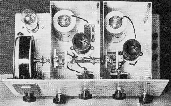
Five Knobs but Single-Control Tuning Band-setting condensers account for the two upper knobs. The others are the tuning, regeneration control and gain. This set is not particularly compact, having been made big enough to sit still on the operating table when being tuned. By George Grammer, Assistant Technical Editor The development of the autodyne receiver for c.w. reception has been a continuous battle for sensitivity and more sensitivity. From the days when a low-loss detector and one-step was the last word in ham receivers to the present era of screen-grid r.f. amplifiers and screen-grid detectors the chief object has been to build sets which would give more noise output for the least signal microvolt input. The latest contribution is the new 56-57-58 series of tubes, which undoubtedly have it "all over" their predecessors. In the meantime some other rather desirable characteristics that receivers should possess seem to have been lost in the shuffle. To be sure, amateurs who have built new receivers whose operation has delighted them, occasionally put forth a few half-hearted claims about "selectivity" - not particularly because the receiver is really more selective but because it's the conventional thing to do. The fact of the matter is that in the set which has become the standard amateur receiver - one r.f., regenerative detector, and one audio - sensitivity and effective selectivity just don't go hand in hand. When you get one you don't get the other, and vice versa. Since both are desirable, it ought to be possible to select whichever of the two is needed under any particular conditions. Then our autodyne receivers would be in a position to give us some real service. Where R.F. Amplifiers Fail Superficially it might seem that unlimited sensitivity would be the height of desirability but, as in all things, there is a limit. That limit is the noise or background level. If a signal is down below that level no amount of amplification in the world will bring it up to readability. This noise level, it should be understood, is not only noise picked up on the antenna, which may at times be very low, but also includes tube noise. Almost any tuned r.f. receiver will give out a hiss that can be heard a couple of feet from the phones with the detector oscillating even if the set is completely shielded and the antenna is disconnected. A lot of it comes from the r.f. stage, as taking out the r.f. tube will show. Our old receivers didn't do that, but the same noise was there, nevertheless. We hear the signals a lot louder today, but it is questionable whether we hear any weaker ones than we used to. The old receivers used to get down to the background level, too.This is not an argument against using r.f. amplifiers nor against high sensitivity, but an r.f. amplifier may not be all beer and skittles. It happens that a regenerative detector is at its best when the incoming signal is weak; that is, the sensitivity decreases rapidly as the signal becomes stronger. R.f. amplifiers therefore don't give the increase in signal strength that might be expected, because the detector sensitivity goes down as the r.f. gain goes up. This would be distinctly favorable were it not for the fact that the detector can't work right on both weak and strong signals. If the circuits are adjusted so that the detector is highly sensitive to weak signals it will be highly unsatisfactory on the strong ones, and vice versa. The unsatisfactoriness arises from the fact that an oscillating detector adjusted for maximum sensitivity will be "pulled in" by a moderately strong signal - that is, the frequency of oscillation tends to become the same as that of the signal - and it is, therefore, difficult to heterodyne the incoming signal to get a beat note. Strong signals, instead of becoming loud in proportion to their strength, simply spatter out over several divisions on the tuning dial and are often harder to copy than weak ones. Worse still, in the course of spattering they wash out any weaker signals in their immediate vicinity. Thus the strange result that a tuned r.f. stage, simply because it brings practically all signals up to good strength, may decrease the effective selectivity of the receiver in spite of the fact that it is supposed to add to it. Selectivity
Inside the Shields Detector at the left, r.f. amplifier at the right. The audio tube sits behind the drum dial in the rear left- hand corner of the chassis. This photo shows the method of ganging the midget tuning condensers. Now that the question of selectivity has been brought up, we really ought to get straight on just what we mean by the word. There are several kinds of it. Usually one thinks of r.f. selectivity as a measure of the ability of the receiver to separate two signals of about the same strength on adjacent frequencies. The difference in this respect between any two tuned r.f.-regenerative detector receivers of the same general type is rarely worth talking about. It depends upon factors not readily overcome in this type of receiver, as James Lamb has pointed out in a previous article.1 We can wipe this kind of selectivity out of the present discussion - it takes a "Single-Signal" receiver to get enough of it to be worth while. But there are other types of selectivity that can and should be obtained in the autodyne receiver. One of these is freedom from interference from local stations working on frequencies somewhat removed from that of the desired signal. This includes interference from local broadcasting stations. If you have a ham neighbor a few blocks away you should be able to copy signals within at least 20 or 30 kc. of his frequency. But very few autodyne receivers we have seen will do it. Local stations usually cut a large swath out of the band and their key clicks can be heard over most of the rest of it, whether the receiver has a tuned r.f. stage or not. As for local broadcasting stations, either you hear them or you don't. If you do, there is no need for us to point out that that type of interference is, to put it mildly, annoying. A second type of selectivity is that which prevents the receiver from causing interference to itself. Queer words, but true. If you get loud harmonics from nearby ham stations or local broadcast stations, make sure that they aren't being generated in your own receiver before telling the other party his transmitter needs some things done to it. A straight autodyne detector coupled to the antenna, and especially a receiver with an untuned r.f. stage, may bring in lots of signals that actually don't exist. A strong local signal will overload the detector or untuned r.f. stage, which then will work as a frequency multiplier and generate harmonics of its own. It would seem that we already have enough legitimate interference without going to the trouble of manufacturing more of it. Selectivity type number three has already been mentioned - the prevention of spreading of moderately strong signals (or so-called "blocking" of the detector) which not only makes them difficult to read but also wipes out weaker signals nearby. This is simply a case of too much signal at the detector. We have seen receivers in which this was so bad that the use of a good-sized antenna when listening on the 3500-kc. band at night was absolutely out of the question. All the signals blocked the detector to such an extent that not a single one of them could be copied. All these things can and should be remedied in the 1933 autodyne receiver. If we can't get real "single-signal" performance from the regenerative set we can at least get the next best thing to it - elimination of practically all interference except that two-beat tuning peculiar to the autodyne detector. Once this is done audio selectivity will be of real help. Eliminating Avoidable Interference Harmonic generation in the receiver can be prevented or at least made negligible by utilizing the selectivity offered by a tuned r.f. stage. Since this type of interference occurs only when the interfering signal is on a frequency which is at the most half of that of the desired signals, a simple tuned circuit will be sufficient to keep out the fundamental frequency of the interfering transmitter. If a harmonic remains in spite of the tuned r.f. stage, then is the time to start blaming the transmitter. The effectiveness of the tuned r.f. stage in cutting out interference from local broadcast stations and nearby amateurs is also unquestioned. Only on detector blocking do we have any quarrel with r.f. amplification. And even this can be overcome by the simplest means imaginable - providing the r.f. stage with a gain control so that a strong signal can be cut down to the point where the detector does not block. An audio volume control is helpless to do anything except keep the phones from rattling. There are two obvious ways of controlling the r.f. gain of a receiver. One is by controlling the signal input, which does not actually change the gain but has an equivalent effect. When we cut down our receiving antennas we are really reducing the signal input, but an antenna of adjustable length would be a rather cumbersome affair. A method used for years in certain broadcast receivers was to connect a potentiometer between the antenna and ground and run the variable arm to the antenna coil on the first r.f. transformer. The potentiometer acts as a voltage divider and permits some regulation of the strength of the signal fed to the r.f. tube. This method, although easy enough to apply, has its disadvantages for ham-band receivers. In the first place, it brings the r.f. right out to the panel, and in the second place the r.f. tube is working its hardest even though the signal input is cut down. In other words, although the signal has been weakened, the r.f. tube is turning out just as much hiss as ever, making the signal-to-background ratio even more unfavorable than it is normally. A better method is to vary the mutual conductance of the r.f. tube so that the actual amplification of the stage is decreased when the gain control is turned down. Then the tube noise will decrease in about the same ratio as the signal strength, leaving it possible to copy weak signals. The actual effect of this sort of gain control is to make an apparent improvement in the signal-background ratio, because to the ear it seems as though the noise decreases a great deal more than the signal does. The characteristics of variable-mu tubes are ideally suited to this type of control. It is only necessary to provide some means of varying the grid bias.
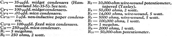
Fig. 1 - The Wiring Diagram Heavy lines indicate grounds which should be made at one point. Heaters (not shown) are wired in parallel. Type 39 and 37 tubes may be substituted for the 58's and 56 shown with no change in the circuit diagram. Resistors R5 and R6 may be omitted if batteries are to be used as plate supply. See text.
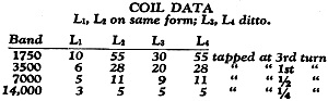
All primaries (L1 and L3) are wound with No. 36 d.s.c. wire. The 3500-kc. grid coils are wound with No. 20 d.c.c.; 1750-kc. grid coils with No. 28 d.c.c.; both close-wound. The 7000- and 14,000-kc. grid coils are wound with No. 18 enameled wire spaced to occupy a length of 1¼ inches. Taps are from the grounded end of detector coils. Coil diameters are 1½ inches. Simple though this may seem - and r.f. gain control really does prevent detector blocking and enormously increases the effective selectivity of the receiver - controlling the grid bias of the r.f. amplifier may cause detuning of the detector circuit if the receiver is not properly built. Inter-locking in tuning between r.f. and detector should be just about eliminated to get full benefit of r.f. gain control, because if there is regeneration in the r.f. stage the amount of it will depend on the mutual conductance of the tube. Furthermore, the detector should be a stable oscillator. These things mean good shielding and proper choice of circuit constants. Before we tried the thing we anticipated that the change in plate resistance of the r.f. tube with varying grid bias might be the cause of an unavoidable change in the tuning of the detector circuit, but experience has shown that detuning from this cause is not noticeable at high frequencies. If detuning exists it can be traced to remediable causes. Detector Stability Getting away from selectivity for the moment, we've had a pet peeve about regenerative detectors for a long time, especially regenerative detectors in a.c. operated receivers. Most of them are far from being stable-enough oscillators. The slightest change in plate voltage will cause the beat note on a received signal to wobble around, a thing which has driven a lot of amateurs to using "B" batteries for plate supply. And when all a.c. supply is used, the way crystal-controlled signals can develop wobbulation is something weird. Unfortunately no oscillator working right on the ragged edge of oscillation, as a regenerative detector does, can be wholly stable, but a lot can be done about it. And the most effective thing to do is a stunt we have been using for years in our transmitters - put some capacity in the tuned circuit. A detector circuit with the largest possible coil and the smallest possible condenser may give the greatest sensitivity, but then the frequency of oscillation is also extremely sensitive to small changes in plate voltage - to say nothing of its penchant for blocking or spreading out on any but weak signals. All the trick circuits we have tried, including the so-called separate regenerator tube, have failed to do a thing about this, but a little dose of our old friend high-C helps amazingly. Maybe there would be fewer plaints in our "Correspondence" columns about rotten signals if more of us had receivers that would do justice to the many really good ones on the air. Just as one example, a blindfolded observer would swear that most of the hams in America had decided to reform in the twinkling of an eye if he had a chance first to listen to the 40-meter band on the kind of regenerative receivers most of us have and then suddenly to be switched over to one with a really stable detector. So far we have largely been talking generalities, but it should be evident by this time that in our opinion the 1933 autodyne c.w. receiver should have certain features. It should have a tuned r.f. stage, ganged with the detector circuit of course for each tuning; it should have an r.f. gain control to prevent detector blocking and increase the effective selectivity; and it should have a detector circuit which is as stable an oscillator as it is possible to make it. Its circuit diagram will look pretty much the same as that of any other tuned-r.f. receiver. The real difference will be in its performance.A Practical Receiver These advantages have been incorporated insofar as possible into the receiver shown in the photographs. Although five controls have been brought out to the panel, the set is in reality a single-control-tuning affair. The two upper knobs (provided with pointers) are band-setting condensers; they are set when coils are changed and need not be touched after that. In the lower right-hand corner is the r.f. gain control. The regeneration control is diagonally below the tuning dial; it, too, need be set only once when coils are changed, since the detector will stay at the "just-oscillating" point over a whole band. To get a fairly high-C circuit for the detector, the parallel-condenser method of band-spreading is used. This, as most of us know, consists of using a fairly large constant capacity in parallel with a small variable capacity. The degree of band spreading will depend upon the ratio of the two capacities and the size of the inductance used for a particular band. The circuit diagram is given in Fig. 1. The panel is of 1/8-inch aluminum and measures 7 by 14 inches. The sub-base is made of a single piece of 3/32-inch aluminum with the corners cut out and edges bent down so that the top surface is 13 1/2 inches by 7 1/2 inches and the vertical sides are about two inches high overall. The sides were bent down with an ordinary small-size bench vise, first being scribed on the under side along the bending line and then worked down to position a little at a time. The two shield boxes are made of 1/16th-inch aluminum, each measuring 4 3/4 inches high, 4 1/4 inches wide and 7 inches deep. The panel constitutes the front of both boxes. The pieces making up the sides of the boxes are fastened together by being screwed to vertical pieces of 1/4-inch square brass rod which has been drilled and tapped to take small machine screws at appropriate points. Similar rods are also used for fastening the boxes to the panels. The lid fits over the tops of both boxes and is held in place by small pieces of phosphor-bronze spring strip which presses against the backs of the boxes when the lid is put on. Although working in aluminum may look difficult to the ham with an ordinary cellar workshop, it requires more care and patience than it does skill. All the work on this receiver was done with nothing but a hacksaw, a bench vise, an ordinary hand drill, a file, a ten-cent kitchen knife, and a few taps. The tuning condensers are 35-uufd. Hammarlund midgets, mounted on the left-hand side of each shield box as shown in the top-view photograph of the set. This type of condenser is readily adaptable to ganging because the shaft projects about a quarter-inch beyond the rear bearing. The condensers should be lined up carefully so the shafts and the center of the drum dial are on the same line, to avoid twisting when the dial is turned. To get a flexible coupling on the rear of the first condenser it is necessary to take off the small spring contacts that wipe on the shaft by bending them down and breaking them off. When this is done it is necessary to make the contact to the rotor plates through the front bearing on the condenser. The rear bearing does not fit tightly enough to make good contact and the condenser will be noisy if an attempt is made to use it. Leave the rear bearing unconnected. The two condensers are connected together mechanically by two small flexible couplings (National) and a piece of 1/4-inch round bakelite rod of appropriate length. A metal rod could be used just as well. The dial is also connected to the first condenser through the medium of a flexible coupling. When lined up properly the whole assembly turns with surprising ease. The two 100-uufd. padding condensers, also Hammarlunds, are mounted on the panel in the positions shown. The coil sockets (and the tube sockets as well) are of Isolantite. These sockets are used not particularly because of any electrical advantages but because they are mechanically rigid and will stand the strain of changing coils without getting bent out of shape. The coil sockets are mounted on small pillars of 1/4-inch metal tubing, just long enough to allow the contacts under the sockets to clear the base. The grid condenser and leak for the detector stage are held from the base by a small metal pillar and are just behind the coil in the detector compartment. Another photograph shows how the parts are placed under the chassis. R.f. rather than artistic considerations dictated the locations of the various parts. For example, there is only one common ground connection for r.f. on the whole set; around it are clustered all the .01 by-pass condensers in the r.f. circuits and all the other r.f. grounds come to this same point. Resistors and audio condensers are mounted wherever it is most convenient to put them, especially if the pigtails provided on them can be used. Occasionally there is an insulating terminal made by riveting a soldering lug to a small piece of fiber which in turn is fastened to the base. The audio choke, a small audio transformer made for broadcast replacement purposes, is mounted on the edge of the chassis at the right. Its primary and secondary are connected in series. This particular transformer has a rather definite peak in the vicinity of 1000 cycles and, as a result, contributes a little audio selectivity to the set. There is little more to be said about the mechanical arrangement of the set. The tuning dial is placed on the left because it is convenient to be able to tune the receiver without getting in the way of copy paper and log books and leave the right hand of the operator free. If you're left-handed, modify the layout to put the dial on the right-hand side. The regeneration control knob is near the tuning knob so both can be worked with one hand conveniently, although not simultaneously. Some Helpful Hints
Informal - but Effective A view underneath the base. No particular precautions here except to keep r.f. leads short and all r.f. grounds at one point. As has been mentioned before, all the r.f. grounds in the set come to a single point. Not only that, all parts of the r.f. circuits that of necessity are connected to the panel or chassis at different points - such, for instance, as the connections made by mounting the tuning condensers - are also connected to the common ground through copper wires. No dependence should be placed on contacts to aluminum for r.f. The circuit used for the detector differs a little in this receiver from the ordinary tickler circuit. It was used because we felt it desirable to use 5-prong coil forms, and in order to use magnetic coupling between the r.f. stage and detector it was necessary to use an oscillating circuit which requires only three connections. The circuit is a Hartley, using the screen and plate in parallel as the anode and having the cathode tapped up on the coil for regeneration. It somewhat resembles the electron-coupled oscillator - several suggestions for this type of circuit have been received from different amateurs and are described in the Experimenters' Section in this issue - but so far as can be told from ordinary observation its performance is not greatly different from the ordinary regenerative circuit. It is used here largely as a matter of convenience. If 6-prong coil forms are available, the use of the regular tickler circuit is recommended, because then condenser regeneration control, which has much less tuning effect than screen-grid voltage control, can be used. Condenser control does not work with this circuit because the plate and screen are in parallel for r.f., and even if there is no by-pass capacity from one to the ground, the other will take charge and keep the detector oscillating; hence the screen-grid voltage control shown in Fig. 1. The band spread with the variable condensers specified in Fig. 1 is not "full-dial" on any band, running about 60 degrees (100-division dial) on 3.5 mc., 40 degrees on 7 mc., and 25 degrees on 14 mc. More spread can be obtained by using a smaller tuning condenser. The Hammarlund 3-plate, with a maximum capacity of 20-µµfd., will widen out the bands considerably. Personally we do not care for the larger spread for a receiver with ordinary selectivity because cranking a high-ratio vernier dial over its whole scale to cover a band is a rather lengthy and laborious operation. This is a matter of individual preference, however. Changing to the smaller tuning condensers will not affect the sizes of the coils nor make any changes in the other circuit values. The Hartley circuit in the detector is a facile oscillator; so much so that the "tickler" - we might call that part of the coil between ground and the cathode tap the tickler - is matter of fractions of turns on the high- frequency bands. The right place for the tap has to be hunted out if the detector is to be controllable with a reasonable value of screen voltage. In this particular set the tap is three turns from ground on 1.75 mc., one turn on 3.5-mc., 1/2 turn on 7 mc. and 1/4 turn on 14 mc.! The taps are made by boring a small hole in the form alongside the point where the tap is to be placed, running a wire through the hole to the pin on the coil form, and soldering to the turn on the coil. All the coils should be "doped" with collodion or a similar material. The 1.75- and 3.5-mc. coils are wound with d.c.c. wire with no spacing between turns; the 7- and 14-mc. coils are wound with enameled wire to the length specified in Fig. 1, spaced out by hand and then doped to hold the turns in place. A fairly even job can be made when the coil has a dozen or less turns. With coils of the sizes specified, the amateur bands will be located with the padding or band-spreading condensers set near maximum on the 7- and 14-mc. bands, and at about 1/3 capacity on 3.5 and 1.75 mc. There will be no need for cut and try if the coil specifications are followed; this band-spread system is an easy one to get into operation because slight variations in coils can be compensated for by the condenser settings. Once the right settings of the padding condensers have been determined for all bands appropriate marks can be put on the panel or small paper or metal scales can be made up and calibrated. Setting the padding condensers is not by any means a hair-line adjustment unless it is necessary to have exactly the same dial readings every time one returns to a band. This is a receiver, however, not a frequency meter. Antenna windings on the r.f. coils run about as with other sets. The primaries for the detector coils are not critical as to number of turns; the values specified give plenty of gain and cause no undue interlocking of tuning. Primaries are close-wound at the bottoms of the coil forms, grid coils at the top. Strictly speaking, the r.f. gain control is not a volume control and it will not reduce all signals to zero strength, since with only one r.f. stage the range of control is limited. Actually, however, it controls volume nicely even though complete cut-off is not obtainable. The purpose of the resistor R4 in Fig. 1 is to increase the range of control over that available by the use of R3 alone in the cathode circuit. With R4 connected as shown, there is a voltage drop across R3, because of voltage divider action, which acts in addition to the normal drop caused by plate-current flow. The total bias with all of R3 included in the circuit is in the neighborhood of 50 volts. A voltage divider consisting of a pair of small resistors (5-watt size) is included in the receiver so that only two plate leads, plus and minus 200 volts, leave the set. The filaments of the tubes are wired in parallel and are brought out to the power supply through another pair of leads, making only a 4-wire cable necessary. The center-tapped resistor across the filament supply should be included in the power pack. This arrangement, which is used by National in their a.c. short-wave receivers, has been found very effective in keeping r.f. out of the power supply cable and in eliminating hum caused by stray r.f. wanderings. If batteries are to be used for plate supply, resistors R5 and R6 can be omitted and a separate lead brought out for the regeneration control. There should be a switch in the negative battery lead to cut off the current drained through R4. and R10 when the set is not in operation. The antenna input on the set is arranged so that a doublet antenna can be used, both terminals on the antenna coupling coil being brought out to binding posts which are insulated from the chassis. The ground post is connected to the common r.f. ground. To use the ordinary antenna-ground connection one of the antenna posts is connected to the ground post and the other used for the antenna. More doublet antennas should be used, however. They improve the signal-noise ratio considerably, as has been pointed out in QST several times, besides doing a better job of picking up DX signals than the 10-foot indoor antennas that many of us use. A good antenna is worth more than an r.f. stage in bringing up signal strength, and it seems rather silly to build a receiver with an r.f. stage and then cut the antenna down to the point where the signals are the same as they would have been with just the detector and a decent antenna - simply because the gain has not been controllable. How it Works A word about the performance of this receiver. On all but 14 mc. the tuning of the r.f. stage and detector are almost completely independent; that is, the r.f. stage can be swung through resonance without causing more than a slight change of beat note on a received signal and without affecting detector oscillation. The 14-mc. band does not do quite as well, but even here the interlocking is not as bad as on most of the tuned r.f. receivers we have seen. The gain control does not affect the detector tuning so long as it causes no change in the voltage applied to the detector plate; in other words, with battery supply the gain control would be entirely independent of frequency. With a conventional a.c. plate supply in which no attempt has been made to improve the voltage regulation there will be a slight frequency change in the beat note of a received signal, its magnitude depending upon the extent to which the plate voltage changes when the gain control is operated. The gain control changes the plate and screen-grid current of the r.f. tube from a maximum of something like 11 milliamperes down almost to zero, and with the particular power pack used in testing the receiver this difference in load caused the plate voltage on the detector to swing something like 15 volts - enough to cause a perceptible frequency change even though the circuits are fairly high-C. Some neon-bulb voltage regulation evidently would be in order.2 The frequency change is rarely bothersome, however, because the gain control usually is set for a level which gives desirable volume and then left alone. The set as it stands is not perfect, of course; nothing ever is. It is a real pleasure, however, to operate a receiver in which the detector does not block, and on which the signals stay put despite normal variations in the power line voltage. It is satisfying to be able to work distant stations almost within beat note of a local ham station. And it is even more satisfying to be able to use a decent-sized receiving antenna and know that when it is necessary to go after the weak fellows the r.f. gain is there and the antenna will be big enough to do some good. 1 "What's Wrong With Our C. W. Receivers," J. J. Lamb, QST, June, 1932. 2 "Stabilized B Supply for the A.C. Receiver," Dekker and Keeman, QST, October, 1932.
Posted June 29, 2023 |
|||||||||||||
 |
|||||||||||||
|
|||||||||||||


|
||||||||||||||||||||||||||||||||||||


