|
January 1935 Short Wave Craft
 [Table of Contents] [Table of Contents]
Wax nostalgic about and learn from the history of early electronics. See articles
from Short Wave Craft,
published 1930 - 1936. All copyrights hereby acknowledged.
|
There are many designs for
multiple-wavelength antennas available. Some use resonant "traps" and specific length
sections of lines to change the effective RF length according to specific frequency
bands, and others employ complex phasing of multiple antennas to a single-point
feed. Doing so allows operation across bands that do not necessarily fall within
or close enough to harmonic ratios, while still presenting decent VSWR to the transceiver
for acceptable performance. Still, nothing beats a single, finely tuned antenna
for each band of operation, or for that matter an antenna whose length is trimmed
to operate at peak efficiency even within sub-bands. It is possible to "match" just
about any antenna impedance to a transmission line and transceiver, there will always
be loses in efficiency and thus loss in power due to resistive losses in matching
networks and transmission lines (where reflected power is dissipated). This arrangement
of a continuously variable length wire antenna is one answer to the problem. It
takes a bit of mechanical aptitude and a willingness to adjust the length with each
frequency change, but after the initial calibration you simply adjust it to marked
points. Designing a fully automatic electromechanical version is well within the
skill set of many Hams.
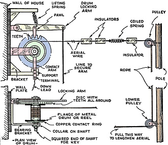
A Variable Wavelength Antenna
 Interesting details of the construction
followed in building a variable wavelength antenna are illustrated above. Interesting details of the construction
followed in building a variable wavelength antenna are illustrated above.
In the early days of short-wave reception every amateur dreamed of having efficient
tuning condensers which would be smoothly and silently variable; then came the variable
grid-leak, volume control, and now variable-mu valves.
This desire to have various features of variable value has caused attention to
be directed to the aerial used for short-wave reception, the idea being to have
the aerial of such a length that it favors a certain wavelength or band of wavelengths.
The natural wavelength of any aerial depends primarily on its length, and the
wavelength (in meters) can be found by multiplying its length in feet by 0.3 and
the result by 4. For example, an aerial 50 feet long has a natural wavelength of
50 x 0.3 x 4 = 60 meters, or, if we wish to know what length of wire to use in order
to obtain a given natural wavelength, we must multiply the number in meters by 3.3
and divide the result by 4. Thus, if we require an aerial with a natural wavelength
of 30 meters, the length of wire required will be (30 x 3.3) / 4 = 24.75 feet or
24 feet 9 inches.
| Natural wavelength in meters |
Length of wire in feet |
| 10 |
8.25 |
| 20 |
16.50 |
| 30 |
24.75 |
| 40 |
33.00 |
| 50 |
41.25 |
| 60 |
49.50 |
| 70 |
57.75 |
| 80 |
60.00 |
The following table (obtained by the above method) will give a close idea as to
the different aerial lengths required to cover the waveband between 10 and 80 meters,
the usual range covered by most dual-range tuning coils for short-wave work:
The free end of the aerial wire is provided with two egg-type insulators, a coiled
spring and another insulator, to which is attached the hauling rope or line which
passes over the top pulley - fixed to the usual wireless pole at the far end of
the garden - down the pole, round the lower pulley and thence back to the house
where it is secured, within easy reach.
With the aerial extended to 14 feet - equivalent to a natural wavelength of 16.8
meters by the formulae given - the Empire transmitter for the African zone was picked
up at fair loudspeaker strength but subject to fading. Extending the aerial another
9 feet gave a length of 23 feet, corresponding to a natural wavelength of 27.6 meters.
The same transmission was tuned in again and found to be louder, with fading not
so deep. The volume dropping to a comfortable loudspeaker strength, while the peak
strength between fades was much greater than ever obtained before. Experiments on
other parts of the waveband have shown that reception is improved by adjusting the
length of the aerial. - World Radio.
(In this article the author referring to "natural wavelength" means the greatest
wavelength at which a grounded antenna will function. In his meter-to-feet conversion
he uses 3.3 as a factor instead of 3.28. These calculations are near enough for
"receiving" purposes but will not serve for computing dimensions of transmitting
antennas. - Editor)
Posted January 17, 2024
(updated from original
post on 2/3/2017)
|


