|
|||||||||||||
 |
|||||||||||||
Micro-Waves Span the English Channel
|
|||||||||||||
We "Baby Boomers" remember a time when cell towers did not present a ubiquitous (and, frankly, ugly) presence across the landscape. Microwave relay towers for television and telephone links could be spotted sitting atop hilltops and mountain ridges in some areas, and giant television and radio station towers sat behind broadcast stations, and multi-element antennas dotted house rooftops everywhere. Our grandparents (Millennials' great grandparents) remember when even microwave relay towers were missing. This 1936 article reports on the first microwave links spanning the English Channel to replace expensive and trouble-prone submerged cable. Part of the impetus, not mentioned within, was the building inevitability of war with Germany and the vulnerability of those communications links to being compromised by Nazi submarines and divers. Micro-Waves Span the English Channel
Fig. 1 shows the towers on top of which are mounted the transmitter and receiver parabolic reflectors. More and more uses for micro-waves are being discovered every day. This particular installation shows how short sections of telephone or other communication transmission lines can be eliminated by micro-wave transmitters and receivers, so long as there are no large intervening objects which might block the transmission and reception. Because micro-waves are quasi-optical in character, the transmitters and receivers must be mounted on high towers.
We can install very low-powered transmitting and receiving stations, the cost of which will be much lower than the average radio station, because of its low power and simplicity. Secrecy can be maintained because these waves can be focused in a very narrow beam, which excludes reception from all directions other than that in which the beam is focused. In the accompanying photographs we have some very interesting views of the micro-wave equipment which is used to cope with just such a condition as mentioned above. This system is used to communicate across the English Channel; one station is located in Lympne and the other in St. Inglevert. The distance between the two stations is some 56 kilometers (about 35 miles). In Fig. 1 we see the two enormous steel structures which support the transmitting and receiving station forming one side of the circuit. The two parabolas which serve to focus the waves for transmission and reception are mounted on the top of this steel structure. The parabolas are approximately 9 3/4 ft. in diameter.
Fig. 2 - The micro-wave generator, which is located behind the parabolic reflector shown in Fig. 3.
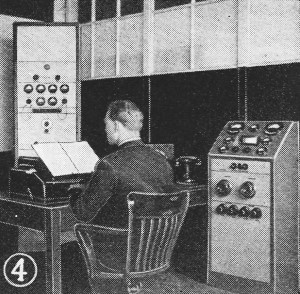
Fig. 4 - The master control room through which the different types of service are routed. Behind these parabolic mirrors is located the micro-wave generator tube and its associated controlling circuits, these are shown in Fig. 2. Fig. 3 is the front view and in the center of the large parabola is a small cup-shaped instrument which further aids in concentrating the focus of the transmitted wave and this cup is supported by three large brackets as can be seen in the photograph. In Fig. 4 we have a view of the control room through which can be routed the various types of traffic which the system handles. This circuit is one of the most versatile of any radio hook-up. Arrangements have been made for high speed printing, regular Morse and radio-telephone communication. The entire system is automatic, insofar as the power supply is concerned. Voltage regulators and other control devices are used to maintain perfect uninterrupted communication. The transmitting system uses a regular modulator together with the necessary amplifier stages in order to bring the voice or code up to a sufficient level for complete modulation. The code and printing machines use an audio frequency tone-generator to supply the necessary modulation for receiving. An elaborate receiver is used wherein the incoming waves are changed to a frequency of approximately 300 kc. and then amplified through the intermediate frequency amplifier, finally detected and amplified similar to the conventional superheterodyne. The output of a receiver can be connected to either a teleprinting device which will print the incoming signals or to an outside line for telephone communication. In other words, the entire installation takes the place of telephone or telegraph cables which otherwise would be used to bridge the gap between the two shores of the English Channel. While we do not know of any truly micro-wave system such as this being installed in the United States, we do have a very interesting installation and one which is very much similar in operation. This American system was developed by the Bell Telephone Laboratories and it bridges Cape Cod Bay from Provincetown, R.I. to Green Harbor, Mass. Here too, due to the large expanse of water between, it was deemed more advisable to use a radio communicating system rather than build a 25-mile telephone line. These transmitters and receivers operate on a wavelength of 4.7 meters and are modern in every respect, inasmuch as a crystal-controlled master oscillator amplifier circuit is employed. The receivers are modern superheterodynes, with the main oscillator of the superhet receiver also crystal-controlled. This system is in use entirely for telephone work and just replaces the ordinary phone circuit. Incoming telephone calls are routed through the radio hook-up in the same manner as they would be if a land wire system were used. The transmitters are mounted on the dependent upon the 100 ft. poles which were provided for this purpose. The antennas are also mounted atop these poles and long transmission lines from the transmitters to the antenna serve as the connecting link. This system is rather complex, in that they have a special tone generator which operates at a frequency of 1000 cycles, interrupted at 20 cycles, for ringing the operator at either end of the circuit. For instance, so modern is this equipment that the operator at the central station at either end of the circuit can make checks upon the operating conditions of the transmitters themselves. Twenty-four-hour-a-day service is provided and to date, faultless performance has been maintained.
Posted March 24, 2023 |
|||||||||||||
 |
|||||||||||||
|
|||||||||||||


 Radio engineers have at last found that the
ultra-short waves or micro-waves as they are sometimes called, can be used to take
the place of telephone or telegraph circuits to particular advantage in some cases.
For instance, if we have two points between which we desire to hold communication
or transmit messages of some type and they are fairly close together (in the neighborhood
of between 10 and 30 miles) and the type of territory between these two locations
does not permit the erection of poles to carry a telephone or telegraph line and
provide communication needed, micro-waves become a very important and useful adjunct.
Radio engineers have at last found that the
ultra-short waves or micro-waves as they are sometimes called, can be used to take
the place of telephone or telegraph circuits to particular advantage in some cases.
For instance, if we have two points between which we desire to hold communication
or transmit messages of some type and they are fairly close together (in the neighborhood
of between 10 and 30 miles) and the type of territory between these two locations
does not permit the erection of poles to carry a telephone or telegraph line and
provide communication needed, micro-waves become a very important and useful adjunct.


|
||||||||||||||||||||||||||||||||||||


