|
|||||||||||||
 |
|||||||||||||
Using a Balanced Aerial System to Eliminate Interference
|
|||||||||||||
QRM and QRN (manmade and natural interference, respectively) has been a problem to be dealt with since the beginning of radio communications. Amplitude modulation (AM) was and is still the most vulnerable because there are so many sources of electrical and electromagnetism generation - both intentional and unintentional. Filters can take care of out-of-band noise, but inband noise needs to be dealt with differently. Some inband interference can be reduced in effectiveness with circuits using specific time constants that address specific noise types. One of the most successful methods for mitigating generic noise is to limit the opportunity for noise signals to enter the system by employing directional antennas. Focusing (literally) reception in the direction of the preferred signal can cause other sources to be rejected. Reflecting surfaces like parabolic dishes and phased element antennas are the two basic choices. In some cases, as is the subject of this article, noise is picked up on the ground and lead-in wires of the antenna system. Constructing a balanced system will cause such interference to cancel before it ever reaches the receiver input. Using a Balanced Aerial System to Eliminate Interference
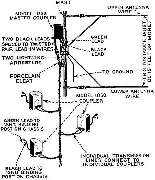
Figure 2 - shows the balanced aerial system installed from a diagrammatic viewpoint. By Thomas C. McClary There is no doubt that even with the increased power of broadcasting stations today, radio interference still spoils reception in many localities. Part of this interference is due to natural causes such as static, but part of it is also due to inductive interference sometimes called "man-made" static, and still in part some is caused by trouble developed in sets, loose connections, worn out batteries and tubes, etc. A further source is that set up by poorly constructed antennas running in the wrong direction or with improperly erected lead-ins. However, even with the most carefully constructed antenna, with thoroughly protected lead-ins, properly checked tubes and latest hook-ups, noises often make for poor reception in some instances. Particularly is this true in metropolitan centers where man-made static has come to have a special meaning of its own to listeners-in. These noises in radio reception are due to the filtering into the receiver circuits and inductive impulses coming from elevators, household electrical machinery and sometimes commercial manufacturing plants near by. Up until recently, engineers have shrugged their shoulders at thoughts of further eliminating these man-made static noises. "The noises are there. If the set, the antenna and the tubes are in proper condition, if the proper filters are installed, what more can be done?" This has been their attitude. Some laymen answered by shutting off their sets entirely. But the technically minded research men have gotten busy with new circuits and antenna systems to try to eliminate trouble. Engineers of the General Motors Radio Corp. have been at work on this problem and have set about to study the causes first and to try to develop means for overcoming interference. At the present time, with many thousands of the installations described in this article in service, they feel they can pronounce their solution generally successfully. Their analyses show that between 60% and 90% of man-made static interference in radio reception is picked up by the lead-in and ground connections and that only a small percentage is picked up on the flat-top antenna proper. Interference noises from refrigerators, door bells, elevators, telephones, etc., are constantly struggling to get in, therefore, on the lead-in wires. The new system is a simple affair involving nothing more complicated than a double antenna installation, with a twisted-pair lead-in feeder connected to suitable balancing transformers at the set. In other words, by balancing out all of the noises picked up on the lead-in and ground system equally, the interference is practically eliminated; the balanced transmission line offering a guarded path through the noise field for the radio signals that are picked up, high in the air above local interference. Local "strays" and inductive noises from the general run of household machinery are thus immediately ejected from the feeder circuit and passed to ground, allowing only the radio signals to operate the sensitive receiver amplifiers. The question, "How can the radio signal, itself, get through this transmission line," may present itself. The answer lies in the difference in potential between the top antenna wire and the low counterpoise wire on the roof, as seen in Figure 1. This potential difference results in an unbalance which permits the fields surrounding the antenna wires to produce an electric potential which will pass the system to the receiver. Fields, however, that are immediately adjacent and surrounding the lead-in wires will cancel each other out. Double Antenna on an Apartment House
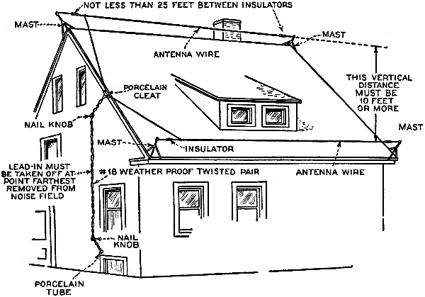
Figure 1 - The essential details for setting up the new interference eliminating balanced antenna system on a flat topped apartment. Installation on a Private Dwelling
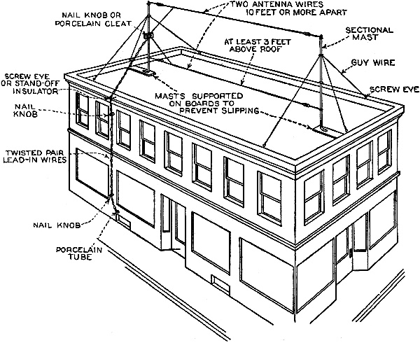
Figure 3. This drawing shows the main details for constructing the new double antenna system and placing it on a home.
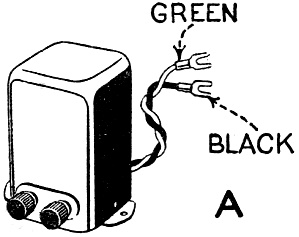
Figure 4A - Shows the transformer connected to receiver while.
Figure 4B - Shows the transformer to be connected on the aerial mast. When the engineers started their investigation the most pressing relief was needed by apartment houses and business buildings where the length of the lead-in could not be governed. The difficulty was overcome by using inductive coupling so that the length of the lead-in with this type of aerial did not matter. The author investigated one of the apartment building systems in operation in Dayton. Ohio. High over the building, above the noise field, is the antenna on tubular masts. Two wires are used, one directly above the other, about 10 feet apart and 50 feet in length. as shown in Figure 1. The engineer explained that the distance separating these wires must be at least 10 feet, and that the lower wire must be at least 3 feet above the roof - 5 feet is preferable. The higher the set of wires are, above any surrounding wires, the better. The antenna wires should be stranded, enameled copper of at least seven strands of number twenty-two for the best results. They should be at least thirty-five feet in length, longer if possible. One hundred foot is the best length, if space is available. Here the important part of the system begins. The wires must be of exactly the same length, otherwise the counter-balance of outside noises is not accomplished. If guy wires are used for the support of the masts, glass insulators should be used at the ends nearest the mast to break any collected energy from being passed on to the antenna. The antenna should, of course, be placed as far from the noise field as possible. A twisted-pair lead-in of number nineteen "outside" weather-proofed wire is used, connected to the antenna wires at the ends farthest from the noise field. Mechanically twisted wire is essential as hand-twisted wire is not sufficiently accurate and a loss of sensitivity and noise elimination results. The lead-in wires are anchored to the mast at a point midway between the two antenna wires so that the length of each lead-in, from anchor to antenna, is exactly even. A porcelain cleat attached to a piece of wood serves as an anchor. Data for the System However, as two lightning arresters will be used. the better plan is to mount them on a solid block of wood anchored to the mast, and use the binding posts of the arresters for the lead-in, being careful to see that the length of the lead-in from its anchor is exactly even. One post of each arrester is used as a terminal for the lead-in wires, while the ground terminals of the arresters are joined together by a jumper wire and grounded preferably on a cold water pipe. The twisted-pair lead-in is carried on to the receiver and connected to an antenna coupler which should be mounted as near the receiver chassis binding-posts as possible. The lead-in wires are attached to the coupler, which in turn is joined to the receiver's "ground" and "antenna" binding posts by means of twisted-pair wires. This same system may be used for any number of receivers up to twenty-five, the only difference being that for a multiple installation a master-coupler should be used between the antennas and the leads-in. In a multi-installation job, the antenna wires should be as long as possible, never less than fifty feet. They should be spaced not less than fifteen feet apart and the lower wire should be not less than from six to ten foot above the roof instead of three to five as is all that is necessary for a single installation. Where a master-coupler is used it is installed on the mast, midway between the two antenna wires - see Figure 2. The lead-in wires are taken from the lightning arrester into the coupler. The two black leads of the master-coupler are then spliced to the main twisted-pair, lead-in wires which connect with the master trunk line. Multiple Installations To establish the proper polarity, make tests with the first receiver attached to the trunk line of the system. Reverse the green and black leads from the individual coupler to the chassis binding-posts. If there is no difference in volume, the polarity of the master-coupler is reversed where it connects with the two antenna wires. If the polarity of the master-coupler is correct, there should be a decided difference in the volume when the leads from the individual coupler to the receiver are reversed. To change the polarity of a master-coupler it is only necessary to reverse the connections to the antenna wire. For houses with a sloping roof, or any other location where the tall mast type of aerial is impractical, the system described is merely laid on its side, see Figure 3. Two wires are used as in the other system, the upper antenna being ten feet or more higher above the ground than the lower one. This is particularly important to remember when installing the antenna on a broad roof with only a slight slope. The lower wire is laid parallel to the upper along the lower edge of the roof. Single System for Homes Four masts should be used, set so as to keep both antenna wires at least three feet above the roof at all times. The greater the height of both of the antenna wires and the greater the vertical distance between them, the better the results. The twisted-pair lead-in should be anchored midway between the antenna wires so that both wires are the same length from the point of anchorage to the far insulators. Both antenna wires must be exactly the same length, exactly parallel, and connected with the lead-in wires at the point farthest from the noise field. No master-coupler is needed for this single installation; only the type 1050 coupler at the set. Once the antenna is completed, continuity tests of the antenna and all lead-in wires should be made. It is important that there be no grounds on either of the two antenna or lead-in wires or between the wires of the twisted-pair lead-in wires, and that the lightning arresters are not short-circuited or grounded. It is also advisable to run a common ground wire to the frames of all metal signs, cornices, etc., on the roof of the building and that conduit or "BX" cables in the building are grounded properly. Both types of couplers are illustrated in Figure 4a and in Figure 4b. It is important to remember that such a system as this is not necessarily a cure-all for all radio interference. Its purpose is to eliminate man-made static or interference originating in the house or in the immediate vicinity where it would be picked up by an ordinary lead-in wire. Also - and what is particularly important - it avoids he transfer, to the antenna system, of interference brought into the house over the light lines. Such interference usually is not picked up by the antenna proper but is picked up readily by the ordinary lead-in wire. By eliminating the possibility of pick-up by the lead-in, noises of these types are effectively eliminated. |
|||||||||||||
 |
|||||||||||||
|
|||||||||||||


|
||||||||||||||||||||||||||||||||||||


