|
|||||||||||||
 |
|||||||||||||
Super Selectivity with Crystals
|
|||||||||||||
This Radio & TV News magazine article on crystal filters will probably be more useful to people responsible for maintenance on old RF systems than for new designs. The technology has come a long way since 1957 when it was published. Crystal filters were heralded as godsends as airwaves became more crowded and simple LC filters could not provide the required Q to prevent cross-channel interference. Of course the problem is many times worse today, but components are better now than then with low-cost integrated circuit front ends that handle a lot of the selectivity issues and SAW filters with better performance than many crystals. Super Selectivity with Crystals
Improved c.w., phone, and single-sideband reception for your receiver with an effective crystal filter. Because of excessive crowding in the amateur bands, an i.f. stage filter in the communications receiver is considered a necessity by most amateur radio operators today and it is for this reason that radio manufacturers include a filter as standard equipment with their higher-priced communications receivers. In their striving for extreme selectivity, manufacturers have resorted to crystal filters, mechanical filters, complicated coil and capacitor filters, and dual conversion in conjunction with a low second i.f. The crystal filter, in one form or another, is still the favorite among hams, however, because of its simplicity, stability, and relative low cost. The filter to be described rivals the best narrow-band mechanical filters available today insofar as selectivity characteristics are concerned; has no greater passband insertion loss than a mechanical filter; and can be constructed for less than the cost of an additional i.f. stage, if the FT-241-A crystals now available on the surplus market are utilized. The filter circuit itself is a modification of the pilot frequency selecting filters used extensively by the British Post Office Department. It can be constructed from standard i.f. stage parts and presents few constructional difficulties, as can be seen from the photographs. Alignment of the filter may present some problems; but, if the instructions given in the text are followed, success is assured.
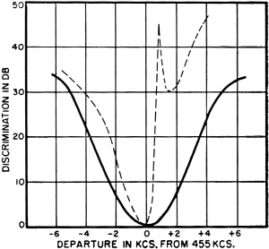
Fig. 1 - Reactance and attenuation curves. The filter consists of two "half-lattice" filter sections connected "back-to-back" in a configuration designed to make it possible to insert the filter into the i.f. section of any receiver having the appropriate i.f, frequency with a minimum of impedance matching difficulty. In addition to impedance matching ease, the "back-to-back" configuration has several advantages over the conventional crystal filter circuit which employs one crystal in conjunction with a phasing capacitor in a single section "half-lattice": Twice the discrimination possible with the usual commercial crystal filter may be obtained; and, since the attenuation outside the maximum rejection frequencies is so much greater than that obtainable with the conventional filter, the external phasing control may be eliminated - the maximum rejection frequencies being permanently fixed by trimmer adjustment during the alignment procedure. Much of the inconvenience experienced with phasing out undesired signals with the conventional filter is thus avoided, since the filter is always in correct operating condition and may be merely switched in and out of the circuit like a mechanical filter. Theory of Operation In operation, each "half-lattice" section of the filter will have a maximum attenuation point ("rejection slot") at the frequency where the reactance of the crystal arm is equal to that of the capacitor arm. It will attenuate in the region where the reactances of the crystal and capacitor arms are most nearly equal and will have a passband where the reactances of the arms are of opposite sign. This is illustrated in Fig. 1. In practice, due to resistance in the circuit, stray coupling, impedance mismatch, and other factors, the attenuation vs frequency curve of one section of the filter will have the form of the dashed curve shown in Fig. 2. As to the bandwidth possibilities of this type of filter, it should be noted that the difference between the parallel resonant frequency and the series resonant frequency of the crystal and its shunt capacitance - (fb-fa) in Fig. 1 - is one limiting factor. With a given value of crystal shunt capacitance, the smaller this difference, the smaller will be the possible maximum bandwidth of the filter. Thus, we may make the filter as narrow as we like by increasing the crystal shunt capacitance, but, with the FT-241-A crystals, we are limited to a maximum passband width of approximately one kilocycle at the 3 db points, assuming a symmetrical attenuation vs. frequency curve similar to that of Fig. 4. A wider passband will result if both attenuation peaks are chosen to fall on one side of the passband.
Fig. 2 - Solid curve is i.f. stage response without filter. Dashed curve shows response with the single-section "half-lattice" filter.
Fig. 3 - Crystal filter circuit diagram.
Fig. 4 - Measured response curve of filter.
Fig. 5 - Set-up used to check the filter.
Fig. 6 - Filter in a.v.c.-controlled stage. It may be noted that with the "back-to-back" configuration it is possible to place one rejection slot on each side of the center-band frequency, as indicated in Fig. 4, or unsymmetrically with both on one side of the center frequency. If the filter is to be used for c.w. exclusively, as was the one built here, the symmetrical arrangement is to be preferred. For phone, the unsymmetrical arrangement is preferable because of the greater passband width possible. The filter, even with the unsymmetrical arrangement, however, may be somewhat too sharp for pleasant phone listening for many operators. Constructional Details The transformers, T1 and T2 in Fig. 3, which were used in this filter were Miller push-pull, 455 kc. output i.f. transformers, one of which was modified by the removal of one input capacitor lead so as to achieve the series-tuned circuit shown in the diagram. The center-tap lead of each secondary coil was brought out through one of the holes in the top of the transformer can. These two operations were performed after removing the fastening nut at the top of the can and withdrawing the entire i.f. coil and capacitor assembly, Extreme care should be exercised in handling the coils as the Litz wire used in the coils is very fragile - breakage of several strands of the wire will result in a change of the d.c. resistance of the coil and will decrease the possible attenuation at the maximum attenuation frequencies, In one of the transformers used here there was a difference of 2 ohms in the d.c. coil resistance as measured from the center tap to each coil end so resistive balancing was utilized. This balancing consisted in the addition of a 2-ohm, non-inductive resistor to the arm connected to the low resistance winding. Resistive balancing, while not absolutely necessary, enables both resistive and reactive balance to be obtained at the maximum rejection frequencies and results in improved filter discrimination characteristics. The balancing resistor is not shown in the circuit diagram but, if one is needed, it should be inserted in the low resistance arm in series with the ungrounded crystal or capacitor electrode, as the case may be. The transformers are mounted skew-wise with a 455 kc. crystal on one side of each transformer as is shown in the photographs. Such a mounting procedure helps to minimize the shielding problem. Since one electrode of the crystal is at ground potential, the crystal may be plugged into its socket so as to have the grounded electrode outside with the other electrode shielded by the transformer can; thus, the crystal is essentially self-shielding. If the filter is to be installed inside the receiver near a potential noise source, the crystals should be shielded more completely; but, since no such difficulty was experienced here, extra shielding was not employed. Capacitors C3 and C4 are securely fastened to the chassis as far apart as possible. By mounting these capacitors back-to-back with the back sides grounded, no extra shielding will be needed - the grounded coax braid and chassis base cover offering adequate isolation. Quarter-inch holes are drilled into the ends of the chassis base cover so as to enable the capacitors to be adjusted after the entire filter is assembled and the cover secured. Since stray capacity may function as a part of the circuit capacity, the chassis and base cover should be in place and securely fastened before alignment. The double-pole, double-throw switch used in the filter is a double section of a two position band switch taken from an old broadcast receiver. The contacts farthest apart were chosen as the input and output contacts so as to minimize feed through. Some apprehension was experienced regarding the feedthrough problem, but all of the connecting leads were made with coax having the external braid grounded to the chassis and the input-to-output capacitance was so low with the switch in the "crystal-in" position that further shielding was found unnecessary. The electrical stability of the filter will depend upon the rigidity and stability of the components, hence, all parts should be well anchored and protected from vibration. As can be seen in the photograph, the coax input and output leads have been securely fastened to the chassis with metal holders to prevent their moving around after alignment of the filter. The crystals used were of the FT-241-A surplus variety, but any set of crystals whose series-resonant frequencies are equal and close to the receiver i.f. frequency may be used. It isn't necessary that the crystals be of the same cut, but a difference in crystal shunt capacitance will affect the position of the attenuation peaks; hence, only the crystals which are to be ultimately used in the filter should be used during the alignment process. Alignment After the filter has been constructed, it is advisable to make a few simple continuity tests with an ohmmeter just to be certain that none of the transformer leads has been broken and that no high resistance solder joints have been made. A high resistance connection may ruin the performance of the filter. The ideal filter alignment set-up is indicated in Fig. 5. A commercial signal generator, a grid dipper, or the b.f.o. in the receiver may be used as the signal generator indicated in the diagram. The b.f.o. would, of course, have to be variable and rewired so as to inject a signal into the grid of one of the i.f. stages preceding the filter, if the receiver were to be used as the amplifier indicated in the test set-up diagram. It is naturally preferable to align the filter in the receiver for which it is intended, since the tuning of the input and output circuits will depend upon the circuits to which they are connected. An SX-43 receiver was used as both the amplifier and voltmeter in the lab here - the S-meter being used as the v.t.v.m. indicated in the diagram. The filter is aligned in three steps: First, the input section to the point marked A (see Fig. 3) is aligned. Second, the output section of the filter, from A through T, is aligned, and; third, the filter is connected to the receiver and both filter and receiver are adjusted. In the first step, the lead connecting the two transformer center taps is cut at the point marked A in Fig. 3. A signal at the crystal frequency is fed into the filter by means of the input coax and the primary and secondary of T, are peaked-measurement being made with the crystal in place by means of the test set-up of Fig. 5; output from A going through coax to the amplifier as indicated in the diagram. The phasing capacitor, C3, is varied so as to place the rejection slot on one side of the i.f. frequency. The closer the rejection slot is to the i.f. frequency, the narrower will be the bandwidth of the filter and the less will be the attenuation outside the rejection frequencies. Half-a-kilocycle from the i.f. frequency is a satisfactory setting. In the second step, the filter is turned around and the identical procedure as was used for the input section is followed to align the second section of the filter. The third step consists in re-connecting the two transformer center taps and adjusting the transformer capacitors once more after the filter is installed in the receiver. If the receiver has no a.v.c. applied to the i.f. stage into which it is desired to insert the filter, the filter may be simply inserted in series with the grid of the i.f. tube, re-adjusting the transformers to resonate at the i.f. frequency. If the stage has a.v.c. voltage applied to the grid circuit, the circuit of Fig. 6 is recommended - the a.v.c. voltage being fed to the grid through the r.f. choke. In any event, some provision must be made for the grid return. If the filter is correctly aligned and the crystals are of the correct frequency, an attenuation vs frequency curve similar to that of Fig. 4 should result. If the FT-241-A crystals are used in the filter, do not take it for granted that the frequencies will be exactly as stated in the specifications. In checking a dozen crystals for frequency variation, over two kilocycle spread was observed in one channel number. It is advisable to purchase half-a-dozen crystals so as to obviate the necessity for edge grinding the crystals to frequency. In operation, the desired signal is tuned in without the filter - the b.f.o. being adjusted so as to give a good note with the signal in the center of the i.f. passband - and the filter is switched in or out at will. The r.f. gain control is run at as low a level as possible, to prevent ringing, and the audio gain is used to adjust the volume.
Posted June 17, 2023 |
|||||||||||||
 |
|||||||||||||
|
|||||||||||||


|
||||||||||||||||||||||||||||||||||||


