|
|||||||||||||
 |
|||||||||||||
Student's Radio Physics Course Lesson 29 - Self-Inductance
|
|||||||||||||
Lesson 29 - Self-Inductance
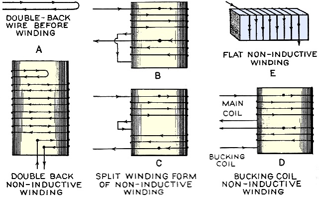
Fig. 1 - Inductor winding variations. Alfred A. Ghirardi The inductors used in radio apparatus take many forms, depending on their particular application. Some have inductances of only a few microhenries, are wound on insulating forms, and have air cores. Broadcast frequency tuning coils may be of the order to 200 to 300 microhenries and may be from 1 to 3 inches in diameter, wound with 50 to 100 turns or so of No. 20 to No. 30 wire. Radio-frequency choke coils having an inductance of 85 millihenries are also used extensively. For shortwave work, smaller values of inductance are used. Iron-core inductances commonly used in audio amplifiers and in the filters of the B power-supply units of radio receivers have a great many turns of fine wire wound on laminated steel cores. Inductances as high as 100 henries are not uncommon in devices of this kind. The windings in inductances as large as this contain thousands of turns of wire. Their particular applications will be studied later. The approximate inductance of iron-core inductor or choke coils built with silicon steel laminated transformer-iron cores may be calculated from the following formula:
A core flux density of 20,000 lines per square inch is assumed. The inductance is in henries, the core cross-section area is in square inches, and the total air gap in inches is determined from the formula.
The size of wire with which to wind the coil is determined by the current the coil is to carry. The wire size may be obtained from the data in a magnet wire table. When an alternating current, or a varying direct current, flows through an inductive winding, a considerable counter-e.m.f. is developed due to the varying magnetic flux. This acts to oppose the flow of the current through the winding, as we shall see later. The large spark noticed when opening the switch in an inductive circuit is caused by the high self-induced voltage which tends to keep the current flowing across the switch gap. Circuits having high inductance should not be opened suddenly, for dangerously high voltages may be developed in them by the self-induction. These may be high enough to puncture the otherwise satisfactory insulation on the wires. Circuits of this kind should be opened gradually by inserting resistance in them to slowly reduce the current to a low value, then finally opening the switch. In some applications of coils where wire is wound up in the form of a solenoid in electrical and radio work, it is desirable that the solenoid should not possess any appreciable amount of inductance. Such windings are called non-inductive windings. For instance, when resistors are made of resistance alloy wire, the wire is usually wound up in the form of a solenoid of many turns, in order to make it compact in size. It is often desirable that the resistor not have any appreciable inductance due to this wound form, as in this case of the resistor coils used in Wheatstone bridges. Self-inductance in a coil may be neutralized by winding one-half of the coil in one direction and the remainder in the opposite direction as shown at (A) in Figure 1. The wire is really doubled back on itself. This is accomplished by folding the length of wire to be used, at its middle point, and starting at this point, winding both halves at the same time as a single wire, until the ends or terminals are reached. The magnetic effects of the current flowing in one direction through half of the total turns is equal and opposite to that produced by the same current flowing in the opposite direction through the other half of the total turns. The magnetic fields thus neutralize each other, and hence no inductive effect is present. The winding is said to be non-inductive. As this method is rather inconvenient when a long length of wire is to be wound up, etc., it is common in manufacturing non-inductive coils or windings to simply wind two wires side by side and join the ends, or to wind the total wire up in the form of two separate coils, each having an equal number of turns equal to half the total turns required, as shown at (B) and (C) of Figure 1, instead of in a single part. Then the proper ends of the coils are connected together as shown, so the current progresses from one end through the two coils in the opposite direction so the magnetic fields are neutralized. The coils need not be wound in the same direction. It is merely necessary to connect them properly so the current flows in the opposite direction in each. At (B) the coils are wound similarly. At (C) they are wound in opposite directions. Sometimes the inductive effect of one coil is neutralized by current sent through a separate "bucking winding" of the proper number of turns, placed near it as shown at (C) of Figure 1. The bucking coil is so wound or connected that its magnetic effect equals and opposes that of the main field. In these methods, the two windings need not be in the same direction. The right-hand rule for the magnetic field of solenoids is employed for working out the proper current directions. Another way of winding a coil that is almost non-inductive is to wind it flattened in shape on a thin flat cardboard or Bakelite form about J1/8 inch thick. Such a coil has practically no inductance because the opposite sides of each turn of wire are so close together that the magnetic fields neutralize, since the current is flowing in the opposite direction in them as shown in (E) of Figure 1.
Posted June 19, 2023 |
|||||||||||||
 |
|||||||||||||
|
|||||||||||||


|
||||||||||||||||||||||||||||||||||||


