|
|||||||||||||
 |
|||||||||||||
Radio Physics Course - Mutual Inductance |
|||||||||||||
Radio Physics Course - Mutual Inductance
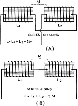
Figure 1 - Inductors may be connected and placed so their magnetic fields either buck each other or aid each other. Alfred A. Ghirardi Lesson 31 The electromagnetic induction due to two independent electric circuits reacting upon each other, is called mutual-induction (see Figure 1). The previous examples of the induction of voltage in the secondary winding of a transformer due to the current flowing through the primary is an excellent illustration of mutual-induction. Parallel conductors carrying independent alternating currents react upon each other by reason of the mutual inductive influence between them. Mutual induction between wires in radio transmitters, and in radio receivers, is often the cause of howling, hum, etc., and certain steps may be taken to prevent this. It is not necessary to again go into a detailed study of the actions taking place during mutual-induction, as this has already been covered during our study of the transformer. It should be remembered that induced voltage is produced in the secondary circuit whenever current in the primary starts to flow, ceases to flow, changes its rate of flow, or changes its direction of flow. The intensity of the induced voltage depends upon, and is proportional to, the rate at which current changes take place in the primary. The higher the frequency, the more rapid is the change of current, and so the greater will be the induced voltage. The greater the amplitude, or rise and fall, of current in the primary with a given frequency, the greater is its rate of change, and the higher will be its induced voltage. The primary and secondary circuits may be simply straight wires near each other, solenoid coils, etc. The total inductance depends upon the connections and the spacing and placing of the coils. From the point of view of the electron theory, the effects of mutual-induction may be explained simply. Electrons are flowing around the primary winding when current is sent through. While this stream of electrons is increasing, it causes electrons in the secondary to flow around in the direction opposite to those in the primary. The secondary electron streams by their movement, produce magnetic forces which exert a backward push on those in the primary, and try to stop their flow. If the primary circuit is opened, the stream of electrons in the primary comes to rest, and those in the secondary reverse their direction of flow and tend to make the electrons in the secondary keep on moving. Whatever change takes place in the stream of electrons in the primary, the electrons in the secondary oppose the change by means of the magnetic forces set up by their motion. The student should check up these forces by applying the right-hand rule to find the directions of the fields in each case, remembering that the right-hand rule refers to the direction of the current flow - which is opposite to the direction of the electron flow. Self-induction can be easily understood by comparing it with the case of mutual-induction explained above. If a coil is connected to a source of alternating current a stream of electrons flows along from one turn to the next. The action between any two turns is the same as if they were two separate coils. As the stream of electrons flow through say the top turn of the coil, they set up a magnetic force which tends to push all the electrons along in the other portion of the coil, that is, tend to increase the current. Two coils may be placed with reference to each other so that a part of the electromagnetic field of one coil passes or cuts through the conductors forming the other coil. Then there is a mutual inductive effect between the coils and they are said to be coupled. The closer together the coils are, the greater are the number of lines of force due to the primary current that link with the turns of the secondary, and the closer or tighter the coupling is said to be. Also the better the permeability of the magnetic circuit, the better is the coupling. The induced voltage across the secondary of such a two-coil arrangement depends upon the sizes of both coils, their relative positions and distance apart, the permeability of the magnetic circuit, and the rate of change of the primary current. All of these physical factors, except the rate of change of the primary current, are collectively called the mutual inductance (M) of the circuit. The larger the coils are, the closer they are to each other, and the more nearly their axes coincide, the greater is their mutual inductance M. Since the mutual inductance possible between two coils is affected by so many variable things, and since the design of radio apparatus is almost entirely tied up with mutual inductances and variations thereof, it is important that we study this subject in detail. In many applications, inductors are connected in series, and are also placed near each other so that magnetic coupling exists between them. The inductance of a coil depends, among other factors, upon the square of the number of turns of wire of which it is composed. Doubling the number of turns makes the inductance 4 times as large, etc. Suppose we have two coils, built exactly alike, as shown in (A) of Figure 1, and having the same inductance. If they are connected together in series but kept apart to prevent magnetic interaction, the total inductance will simply be equal to the sum of the two. However, if they are connected in series and brought close together, we can have many conditions. If they are placed so the direction of current flow and hence the lines of force of one are exactly opposite in direction to the lines of force of the other as shown at (A) of. Figure 1, the total inductance will be zero. This is called the "series opposing" position. If they are connected together in series, with the currents flowing in the same direction and are brought up to each other so that every line of force of the primary links with every turn of wire of the secondary, and every line of force of the secondary links with every turn of the primary, and the fields of each are in the same direction, the result is the same as though we had a single coil made up of the two coils together, that is, a single coil having twice as many turns as each of these coils. This condition is shown at (B) of Figure 1. Since the inductance is proportional to the square of the number of turns, it is evident that this combined inductance is equal to 2X2 or 4 times that of either coil alone. Therefore the combined inductance of two similar coils connected and placed so as to be "series aiding" is four times that the self inductance of either single coil. In the case of series-aiding coils, the total inductance is made up of the self-inductances of coil 1 and coil 2, the mutual inductance due to the lines of force from coil 1 linking with coil 2, and the mutual inductance associated with the lines from coil 2 which link with coil 1. These two latter mutual inductances (M) are equal, since the coils are the same. Therefore L = L1 + L1+ 2M. Since L1 = L2 and M = L1 if we substitute these values for L in the above formula, we have L= L1+L1+2L1 from which L = 4L1 where L is the total inductance. If some of the lines of force from one coil do not link with the other-as is the case especially if air forms the core - the total inductance will be less than four times the inductance of one coil in this case. In the series opposing case it will be less than zero. In any general case the total inductance of two coils of any inductance value, connected so as to be series-aiding, will be: L = L1+ L2 + 2M If they are connected in series-opposing, the total inductance is: L = L1 + L2 - 2M In order to know then just what the total inductance will be, the degree of coupling must be known. The term "coefficient of coupling" enables us to predict just what the total circuit inductance will be if the amount of coupling is known. Of course the coefficient of coupling depends upon the total inductance in the primary and secondary circuits as well as upon the mutual inductance between the inductances. The coefficient of coupling is really a measure of the ease with which energy may be transferred from one circuit to the other. The coefficient may be found from K = M √L1 L2 all units being in henries, microhenries or millihenries. The maximum possible value of K is of course 1.0. This is called unity coupling. The value of 1.0 is only approached in well designed iron-core transformers where there is very little magnetic leakage. In air-core transformers the coupling may be very "weak" since a large portion of the lines of force of the primary may never reach the secondary. A low value of coupling for this type of coil would be about 0.1, and a high value 0.7. In a well designed iron-core transformer, coupling as high as 98 or 99 % (K = 0.98) may be obtained, depending upon the design and the amount of magnetic leakage present. The mutual inductance depends only upon the two coils, and the coupling between them or M = K √L1, L2. The coefficient of coupling K, between any two circuits depends upon the total inductance in each circuit. Thus if one of the two circuits had two inductors in series, the total combined value of the two series inductances in this circuit would be substituted for L1 in the above formula for K. *Radio Technical Pub. Co. Publishers, Radio Physics Course.
Posted June 23, 2022 |
|||||||||||||
 |
|||||||||||||
|
|||||||||||||


|
||||||||||||||||||||||||||||||||||||


