|
According to an FCC document
"11th
Annual Report, Federal Communications Commission, Fiscal Year Ended June 30,
1945," Chapter VIII - War Activities, "The Radio Intelligence Division,
established in 1940 to give America wartime protection from misuse
of the ether lanes by spies or other illegal operators, discovered
46 unlicensed stations during the fiscal year, investigated 1,445 complaints
of suspicious transmission and of interference. These complaints were received
from the general public, commercial communication companies, Government agencies,
and the military. During the year, the RID furnished fixes to 283 planes which
were in distress. A total of 996 requests for assistance of all types to planes
was received. The RID took 85,031 bearings. A number of alerts originated totaled
25,000. This figure represents the number of instances in which an origination
was made by each monitoring station equipped with long-range, high-frequency
direction-finding facilities for the purpose of obtaining synchronized bearings
from a net of direction finding stations upon a particular radio station under
surveillance. To facilitate its task of identifying the thousands of stations
heard around the world so that the enemy, subversive or unlicensed stations
may be spotted instantly, the RID compiled an additional 200,000 index cards
for its files. These records show the operating characteristics of stations
logged or otherwise monitored. In accordance with a budget reduction, the personnel
of the RID was reduced from 468 to 328. The number of secondary stations was
reduced from 59 to 28, of which 13 were equipped with long-range, high-frequency
Adcock type radio-direction finders. The number of primary stations, totaling
12, was maintained." See also "The
FCC's RID and Japan's Surrender."
Radio Intelligence
 By Oliver Read, W9ETI By Oliver Read, W9ETI
Managing Editor, Radio News
An eye-witness report on the little known technical aspects of the RID.
The Radio Intelligence Division (RID) of the Federal Communications Commission
is one of the government agencies least known to the American public. Up to
the present time little information has been forthcoming showing the important
functions of this non-military unit. Highly important in peace - the RID has
been performing one of the most essential tasks in wartime - ridding this country
of illegally-operated radio stations, most of them by spies of foreign powers.
Furthermore, they have saved hundreds of lives by locating lost aircraft. Millions
of dollars worth of vitally needed planes have also been saved from an untimely
crack-up.
The RID was organized several years ago by George Sterling, W3DF, who still
directs all activities as Chief. Assisting in this important work are Charles
Ellert, W3LO and Stacy Norman, W70K, all prominent radio amateurs.
Principal functions of the RID include: Maintaining a continuous policing
of the entire radio spectrum to insure against unlicensed transmissions and
taking appropriate action to suppress such operation; locating and eliminating
interference to licensed stations; maintaining a continuous surveillance of
licensed stations in cooperation with the Field Division of the Engineering
Department, FCC; making intercepts of foreign non-military radiotelegraph traffic
for the use of other civilian agencies of the Government, and recording foreign
broadcasts for the Commission's Foreign Broadcast Intelligence Service.

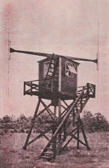
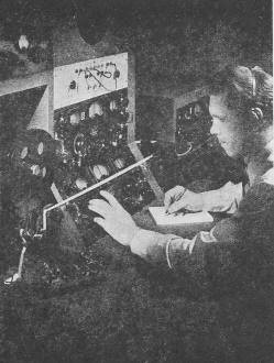
Adcock direction-finder - so critical in balance that a
spiderweb across the transmission line will upset calibration. Operator is
K. W. Miller. W5AOC. Asst. Supv.
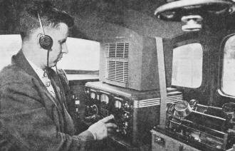
Interior of RID mobile unit. Operator is adjusting the Hallicrafters
SX-28 receiver while signal is being transcribed on Telecord wax cylinder machine.
Wheel, upper right, is part of direction finder.
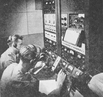
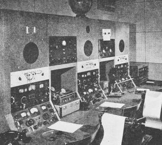
Operators of the "ether patrol" searching for a lost aircraft
(LOP) from the Cruising Room at Allegan, Michigan. Receivers operate continuously
day and night.
Other important activities are performed by the members of the RID. Included
are the rendering of emergency direction finding service to civilian and military
aircraft, training personnel in radio intelligence work for other Government
departments and foreign countries, and the furnishing of equipment to various
Government departments, etc. The RID is comprised of twelve primary monitoring
stations and thirty-two secondary monitoring stations located throughout the
United States, its territories and possessions. All of the primary stations
and secondary stations within the United States and all the secondary stations
in the territories are linked together for instantaneous communications either
by private tieline or by radio links. The activities of the monitoring stations
is coordinated from three Radio Intelligence Centers. Work on the East Coast
is coordinated from the Center in Washington, D.C., work on the West Coast from
the Center at San Leandro, near San Francisco, and work in Hawaii from the Center
in Honolulu. Each of the primary monitoring stations is located on a large tract
of land to permit erection of extensive receiving antennas. These stations are
also located so as to be as far away as possible from electrical interference
which would be experienced in or near cities.
A typical primary monitoring station, located near Allegan, Michigan, was
visited by the editors of Radio News in order to get firsthand information on
its activities and to meet the personnel of the RID. Supervising at Allegan
is William J. Hoffert, W5HVB and his assistant, Kenneth W. Miller, W5AOC. We
found that 90% of the personnel at Allegan were licensed amateurs. Their experience
had given them a valuable background for this important work. The personnel
in the RID Division of the FCC at this station includes four monitoring officers
and twelve operators. Working in shifts, these men "patrol the ether" twenty-four
hours a day.
Associated with each primary station are a number of satellite stations known
as secondary stations. Location of these are chosen with regard to density of
population and radio activity. They are situated on leased property at locations
that permit good radio reception, the great majority of them being within the
continental United States.
In addition, there are associated with each secondary station one or more
special mobile units that are equipped with radio receivers, equipment for taking
radio bearings at short range, and equipment for recording the radio signals
which are intercepted. At times, two or more of these mobile units work together
on a particular case. For the purpose of coordinating their work many of them
are equipped with radio to communicate with each other.
It is interesting to note that practically all of the equipment at the RID
stations is in continuous operation. Mr. Hoffert pointed out, for example, that
none of the receivers had required a major repair since they were installed
in 1941. The equipment used at this station is typical of that used in all RID
stations. In the "Cruising Room," for example, are one Bendix frequency standard;
six Hallicrafters SX-28 and one S-27 receivers; one Hallicrafters HT-7 frequency
standard; one National 1-10 receiver and one RCA 10kc. inverter with demodulator.
In addition are the regular teletype-writers and emergency radio channels used
for communications should the teletype fail. The operators in this cruising
room tune the entire radio spectrum continuously in their search for unidentified
signals. An Intercom connects to the two Adcock direction finders. This is used
to "alert" the DF operator when a long-range bearing is required.
When it is necessary to report unidentified intelligence, operators in the
"Intercept Room" record the transmissions on ink recorders, discs or cylinders.
Equipment in this room includes a Bohme ink recorder, seven Hallicrafters SX-28
receivers, two Memovox recorders, Telecord wax cylinder machine and a Telrad
frequency standard. A special receiver designated as SSR-202 (SX-28 with additional
i.f. channel) is employed. This latter unit is capable of separating badly scrambled
transmissions and by the use of special circuits (restricted at the moment)
are able to bring in these signals clearly for recording.
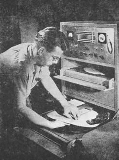
Changing a paper disc on one of the Memovox recorders in
the Intercept Room. An hour's intelligence is recorded on each side.
William J. Hoffert, W5HVB, RID supervisor at Allegan, recording
high speed code on Boehme tape machine.
There are six crystal-controlled standby frequencies always available. A
Transmitter House far from the main building houses three RCA ET-8019 200 watt
transmitters. These are operated by remote control from the Cruising Room. An
Onan 5KW gasoline-driven generator supplies power to the transmitters in case
of failure of the 60 cycle line supply.
We mentioned before that it is the job of the RID to police the entire radio
spectrum. In order to detect subversive or other illegal use of radio it is
necessary for the monitors at all of the stations to maintain continuous patrol
of the ether. These monitors must be able readily to identify the hundreds of
thousands of radio signals which they hear daily. There are a number of means
by which radio signals can be identified. For example, checking call letters,
checking frequencies, checking operating procedures, analyzing the traffic and
analyzing technical characteristics of the signal, such as its strength, hum,
echo, fading, and the particular style of the operator.
If it is still not possible to identify a signal by the application of these
or similar criteria, it then becomes necessary to search and locate the transmitter
by means of radio direction finding.
The RID stations make use of a highly perfected direction finder designed
from the principles discovered by the Englishman, Adcock. It is known as a balanced
H type and is shown on page 25.
A simple analogy to show how this direction finder operates would be the
familiar battery operated portable radio set in a carrying case. These receivers
use a built-in "loop" for picking up the signal. The loop consists of a number
of turns of wire wound on a narrow rectangular framework usually fastened within
the carrying case, and in some cases, mounted on the outside but always in a
vertical position. Our readers are familiar with the fact that such a receiver
has marked directional properties and that some stations are heard with much
greater signal strength than others. These discriminations against a certain
station may be altered by changing the position of the loop. This is basically
the function of the direction finder.
If a pointer is attached to the loop and is made to traverse a circular scale
graduated in degrees (marked from 0 to 360 degrees) it is possible to ascertain
the true direction of a given radio station by noting the position of the pointer
with reference to the scale when a null is obtained. This null is the point
where the signal is no longer heard and occurs when the loop is "broadside"
to the arrival of the signal.
In using a loop direction finder, the scale reading opposite the pointer
is determined not only by the direction of the radio station with respect to
the location of the loop but also by the position of the zero graduation on
the circular scale. If the zero mark or graduation is placed so that it coincides
with true north (which can be done either by revolving the scale or the object
to which it is fastened) then the radio bearing obtained will be with reference
to true north. It is advantageous to do this because the radio bearing can then
be projected on a suitable chart or map in much the same manner as plotting
a ship's course.
If only one direction finder is used, there is no way to ascertain the exact
point on the projected bearing line which would correspond with the location
of the radio transmitter. However, if an additional direction finder is used
so as to provide a bearing from a different location, and this bearing was drawn
on the map, then the intersection between the first and second bearing lines
will correspond to the radio transmitter location. This is so because there
can be only one common point between two straight lines, namely, at the intersection.
The point of intersection between two such projected radio bearings is called
a radio "fix." One direction finder could be moved about to provide two or more
bearings; however, this process is too slow for obtaining a fix when time is
important.
A "ham's paradise." Any type of signal may be recorded in
the Intercept Room on tape, wax cylinders, or paper discs for observation and
reference.

Transcribing copy from Boehme tape. Operator controls speed
by foot.
Even with the very best direction finders, the precision with which a radio
bearing can be obtained is seldom better than 1 degree. In other words, the
observed radio bearing may differ from the true or correct bearing by the amount
mentioned. Among radio direction finder technicians this degree of precision
in equipment performance is often referred to as an accuracy of plus or minus
1 degree. Precision is an important factor in selecting direction finder locations
because it directly affects the accuracy of a radio fix which is one of the
basic considerations in the evaluation of radio bearings.
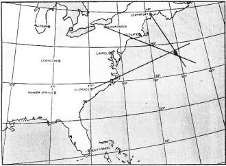
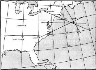
When dealing with three radio bearings, the inaccuracy in the individual
bearing causes the radio fix not to appear as a one point intersection of three
lines but as a triangular area often referred to as a "cocked hat." If the direction
finders are poorly placed, the area encompassed by this "cocked hat" may be
large and the ability to estimate the position of the radio fix becomes most
difficult. Reference to the charts will show that in the case of a two bearing
fix and that if either has even 1 degree error, the point of intersection of
the projected bearing would shift greatly due to the small angle formed by the
bearing lines. It can be shown mathematically and, in fact, it is fairly obvious,
that for a given bearing inaccuracy the determination of the radio fix is subject
to the least error if the radio bearing lines intersect at an approximate right
angle of 90 degrees. The size or the extent of the area enclosed by the "cocked
hat," formed by the projection of three radio bearings, is no indication as
to the probable accuracy of the radio fix. If two or all three of the bearings
are subject to observational errors, it is entirely possible to have all three
bearing lines intersect at a single point, but the radio fix may not at all
correspond to the actual position of the radio transmitter. For this reason,
a three bearing radio fix can never be classed as being reliable and even when
the angle between the outside bearing lines approaches the favorable 90 degree
cut such a radio fix can never be rated better than fair.
In order to obtain a good radio fix, it is practically necessary that at
least four radio bearings be taken. It has been found that by taking a fourth
bearing, or even more, that these will give confirmatory information which enables
experienced personnel to judge whether the quality of the radio fix is good.
By taking into account the angles between radio bearings, the distribution of
the radio direction finders with respect to the probable radio fix, and the
effect of propagation conditions on the accuracy of the radio bearings, remarkably
good radio fixes are possible. The process of taking into account these factors
is called "evaluation of bearings." However, for long range work more elaborate
equipment is required due to the nature of radio propagation.
When a signal is emitted from a radio transmitting antenna, a portion of
the total signal power leaves the antenna in all directions and travels parallel
to the surface of the earth. In accordance with well-known physical laws the
signal strength decreases as the distance between the transmitter and radio
receiver and continues until the signal strength or intensity is too low to
actuate the receiver. This is commonly known as the ground wave - the distance
range of which does not generally exceed 100 miles except under certain favorable
circumstances. Within the ground wave distance range the loop direction finder
will function satisfactorily. The mobile units of the RID operate within this
range when taking their short-range bearings.
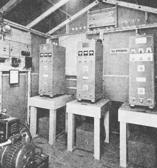
These three RCA transmitters are operated by remote control
from the Cruising Room. They are used for emergency communications to other
primary stations.

Operators on duly at Laurel, Md., recording foreign propaganda.
The receivers shown are Hallicrafters SX-28's while the recorders are Memovox.
Part of the total signal power is emitted from a radio transmitting antenna
at various angles above the ground. This portion of the signal travels skyward
until it reaches a region known as the Kennelly-Heaviside layer. This region
consists of electrified particles created as a result of solar radiations striking
the outer limits of the earth's atmosphere. In accordance with well-known physical
laws, some signals are reflected and returned to earth where they are capable
of actuating a radio receiver which may be thousands of miles from a radio transmitter.
A signal arriving by this means is known as the skywave signal. In the process
of signal reflection, an electrical change in signal occurs resulting in the
production of two signal components one of which is said to be horizontally
polarized and the other vertically polarized. The combination or resultant of
these two components forms. the skywave signal. Inexperienced personnel, unable
to distinguish between ground wave and skywave signals, frequently attempt to
take radio bearings on skywave signals with loop-operated equipment with the
result that the radio fix obtained by projecting such bearings is invariably
in error.
Using an aerial of special design, it is possible to obtain the same directional
characteristics as that possessed by a loop and the horizontally polarized error
inherent in the loop is reduced to a negligible value. This type of signal collector,
together with its associated receiver (Hallicrafters SX-28) is commonly called
the Adcock direction finder. The dipoles, or collecting portions of the equipment
consist of a rotating beam and balanced H antenna. Each of the vertical dipoles
are approximately 20 feet long. The spacing between these vertical elements
is also approximately 20 feet. These elements, resembling the letter H, are
supported at their centers and interconnected by a horizontal transmission line
from the midpoint of which signal energy is taken and delivered to the radio
receiver. The beam is supported at its center on a small hut on top of a tower
approximately 20 feet above the ground.
Unlike the ordinary radio receiver used for broadcast station reception,
both the loop and Adcock type of direction finders must be located at sites
carefully selected to minimize those effects which are capable of introducing
errors in radio bearings. In general, such locations must be out in open flat
country, free from electrical noise-producing industrial areas, free from overhead
wiring, such as aerials, power, telephone and telegraph lines, free from barbed
wire and other metallic fences, and free from wooded areas. In order to keep
the site error low, separation from the direction finder to the obstructions
mentioned must be not less than about 350 feet.
The basic reasons for providing good base lines for radio direction finders
has already been discussed. From experience gained prior to Pearl Harbor, and
that obtained in dealing with the many and varied problems since that date,
the RID has evolved a direction finding network which has proven to be adequate
in quickly locating the source of any radio signal. A network capable of rendering
satisfactory service over the entire continental United States, its territories
and possessions, is necessarily extensive because of the physical laws that
govern radio propagation. For example, a radio transmitter located in New York
City and operating on frequencies below 5 megacycles would have a distance range
of only a few hundred miles during daytime hours. In order to obtain a sufficient
number of radio bearings to obtain a good radio fix, it is obvious that a substantial
number of direction finders would be necessary east of the Mississippi River.
It is also obvious that direction finders west of the Mississippi would be worthless
in the problem cited because of the inability to hear the signal of the station
on which bearings are desired. For such reasons, the RID direction finder system
is composed of several networks, each reporting to its regional clearing house
of information called an Intelligence Center. Here the efforts of each direction
finder are directed, coordinated and evaluated.
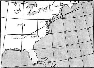
A two-bearing fix can never be considered as being satisfactory.
A three-bearing fix gives a "cocked hat" triangulation.
A fourth bearing gives confirmatory information for fix.
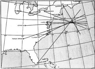
Highly reliable eight-bearing fix is known to be accurate.
A major factor in the successful coordination of a direction finder network
is communications. Of the hundreds of radio signals appearing in a small section
of the radio frequency spectrum, the problem of directing the efforts of several
direction finders to a specific signal to make certain that all bearings are
taken simultaneously on the desired signal requires a thoroughly reliable communications
circuit from each direction finder to its intelligence center. In the RID this
is accomplished by using both radio and wire teletypewriter service, the former
being used in the outlying territorial and secondary direction finders and the
latter in the important primary stations.
In performing operations leading to the location of an illegal or clandestine
transmitter, the direction finding nets are operated as one net and controlled
from the Division's Headquarters in Washington. Intelligence Centers control
regional nets for the purpose of rendering emergency direction finding service
to aircraft, locating the sources of interference to radio services and for
certain other operations.
It has been found that the accuracy of a bearing will vary with the time
of day, atmospheric conditions along the route of propagation from the transmitter
to the direction finder, and a variety of other factors. The accuracy of the
fix, in turn, will depend on how well the bearings are evaluated. To cope with
this problem, the RID has made extensive studies of the variation of bearings
taken through the so-called "twilight zone" and other atmospheric peculiarities,
and has charted the corrections to be applied to observed bearings to compensate
for such conditions as twilight and distance. The RID furthermore has made a
study of radio propagation factors, the effect of the sun spot cycle, etc.,
on long range direction finding.
It is a routine procedure for the RID personnel to take periodic "check bearings"
on various known stations to determine any deviation in the accuracy of the
bearings supplied by each direction finder. As a result, RID has developed a
whole series of check-bearing procedures by which it can determine from day
to day what deviations may be expected from particular direction finders on
particular frequencies and at particular times.
There is an inevitable tendency for radio operators taking bearings on known
stations to approximate these bearing readings to the bearings which they know
in advance to be correct. The RID has developed its check-bearing procedures
to such an extent that where an operator turns in a bearing on a known station
which is more accurate than conditions warrant, his bearing can be questioned.
While direction finding is absolutely essential in the location of subversive
or illegal transmitters, it has many other uses. For example, the same techniques
are employed in tracking down the source of interference to licensed broadcast
stations. Such interference may come from another station which is operating
improperly or from some medical or industrial device using equipment which generates
radio interference. One of the most important uses for radio direction finding
techniques is fixing the position of lost aircraft. Bearings can be taken on
a plane which does not know its position and the pilot can then be advised by
radio of his position and the proper course to fly to bring him to his desired
destination or to a safe landing.
The RID has standing requests from a number of government agencies which
require it to intercept the traffic of thousands of foreign non-military stations.
The simplest form for making an intercept is for the operator to listen to the
transmission through headphones and simultaneously type the message. The maximum
speed for this type of operation rarely exceeds 40 words per minute. Sometimes
it is not feasible to transcribe the message simultaneously with its transmission
and it is then necessary to make a Dictaphone cylinder or a flat disc recording.
Frequently, radio intelligence transmissions instead of being sent by manual
keying are sent by mechanical devices at speeds up to 500 words per minute.
These high speed transmissions cannot be transcribed manually. Accordingly,
for this type of transmission a high speed tape recorder is employed. It is
possible for operators without any skill in aural reception of radio signals
to learn to accurately read such tape and transcribe it on a typewriter.
Another type of tape recording device is the Hellescreiber which, instead
of printing dots and dashes, actually prints letters and words on the tape.
It should be pointed out that frequently single monitoring stations, because
of the physical laws which govern long distance radio transmission, cannot obtain
a full and complete copy or recording of the radio signal being intercepted.
To remedy this it is necessary to have two or more monitoring stations intercept
the same transmission. When, because of fading, the signal cannot be received
intelligibly at one point, it is possible at that very same moment to receive
it clearly at another point. By putting together the incomplete or "broken"
copy received by several monitoring stations, it is possible for the RID to
furnish the interested government agency with a "solid" copy of the foreign
transmission.
The RID also records voice broadcasts and radiotelegraph press dispatches
from foreign stations throughout the world for the Commission's Foreign Broadcast
Intelligence Service. For this work, RID maintains five units which are known
as Broadcast Recording Units. These units are in addition to the physical set-up
previously described and they are located at Silver Hill, Maryland; Hato Rey.
Puerto Rico; Kingsville, Texas; Hayward, California, and Portland, Oregon.
After V -day we expect to see an ever-increasing demand on the RID for the
taking of bearings on lost aircraft piloted by private fliers. The Civil Aeronautics
Administration expects a tremendous increase in air traffic. Even with new electronic
devices, many of them automatic, there will, still be many planes lost and it
will be the job of the RID to find them and to direct them to a safe landing.
The finding of boats of many varieties will also make it necessary for the RID
to expand its activities.
We point with pride to the fact that 70% of the total personnel of the RID
are licensed radio amateurs - just another "case history" which should point
out to the public that without these hobbyists America might still be faced
with the problem of ridding the country of foreign spies - operating illegal
transmitters and transmitting vital information to the enemy. Thanks to Radio
Intelligence-such clandestine stations are now almost non-existent.
Posted March 18, 2021
|


