|
September 1932 Radio News
 [Table
of Contents] [Table
of Contents]
Wax nostalgic about and learn from the history of early
electronics. See articles from
Radio & Television News, published 1919-1959. All copyrights hereby
acknowledged.
|
 "Don't
forget who brung you to the dance," is a variation of the old adage that admonishes
you to remember who/what it was that provided the opportunity to be where you are
now. It aptly applies to radio communications of all sorts. This short article from
a 1932 edition of Radio News discusses the advent of radio beacon installations
across America to facilitate air navigation during inclement weather. Before there
was a Federal Aviation Administration (FAA), the Department of Commerce handled
commercial air traffic for passenger and cargo payloads. Aviation was on the verge
of becoming a very profitable industry (the
Douglas DC-3
would make that happen in 1935) and it was necessary to develop airspace controls
to ensure safety and smooth operations. Early direction finding equipment used a
directional loop antenna to indicate the bearing (not necessarily the heading, due
to winds) to a ground-based broadcast station. Audible signals indicated whether
the aircraft location was to the left or right of the station. Visual indicators
would later provide course deviation information. Aside from GPS, radio beacon navigation
is fundamentally the same today as it was in 1932, only with more precision, greater
reliability, and more reference stations. If you don't know a VORTAC station when
you see it, take a look to the upper left - yep, that's what those things you see
sitting in fields all over America are! "Don't
forget who brung you to the dance," is a variation of the old adage that admonishes
you to remember who/what it was that provided the opportunity to be where you are
now. It aptly applies to radio communications of all sorts. This short article from
a 1932 edition of Radio News discusses the advent of radio beacon installations
across America to facilitate air navigation during inclement weather. Before there
was a Federal Aviation Administration (FAA), the Department of Commerce handled
commercial air traffic for passenger and cargo payloads. Aviation was on the verge
of becoming a very profitable industry (the
Douglas DC-3
would make that happen in 1935) and it was necessary to develop airspace controls
to ensure safety and smooth operations. Early direction finding equipment used a
directional loop antenna to indicate the bearing (not necessarily the heading, due
to winds) to a ground-based broadcast station. Audible signals indicated whether
the aircraft location was to the left or right of the station. Visual indicators
would later provide course deviation information. Aside from GPS, radio beacon navigation
is fundamentally the same today as it was in 1932, only with more precision, greater
reliability, and more reference stations. If you don't know a VORTAC station when
you see it, take a look to the upper left - yep, that's what those things you see
sitting in fields all over America are!
Radio Aloft!

Modern airport and plane radio equipment not only provides an
operations communication medium, but also a guide for blind flying and landing under
weather conditions which would otherwise offer an insurmountable hazard to 'planes,
pilots and passengers.
...in Private and Transport Flying
By John B. Brennan, Jr.
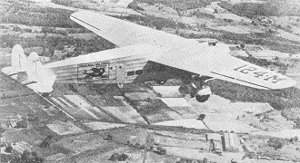
Picture yourself on a plane, one of those big
tri-motored affairs, which has just taken off from the Newark
Airport, bound for Cleveland. Although you may not have known it, the pilot, previous
to the take-off, scanned the weather dispatches at the Operations Office and found
that he would have good weather along the major portion of his course but on arriving
in the vicinity of Cleveland he might expect haze and fog.
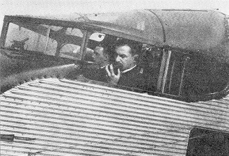
Once up in the air his co-pilot, who is also the radio operator, has donned the
headphones, switched on the radio receiver and has tuned it in to the signals being
transmitted by the radio range beacons, of which, on his course, there are three;
one at New Brunswick, New Jersey, one at Bellefonte, Pennsylvania, and the other
at Cleveland, Ohio, all on direct route.
In clear weather it is not necessary to depend on the radio range beacons for
an indication of the true course since visual searchlight beacons and markers on
the ground at these searchlight points are situated along the course every ten miles.
Therefore, having satisfied himself that the radio receiver is functioning properly
the co-pilot tunes it to another wavelength so that he may listen to the many radio
ground stations located along the path of his course and to the major aeronautical
ground stations located at the scheduled stopping points along his route and which
are a part of the vast radio chain system operated by the airways organization which
employs him.
Thus, speeding along at some ninety to one hundred and ten miles an hour, the
plane in which you are comfortably seated is always in constant communication with
some radio station on the ground and your pilots are being advised periodically
of flying conditions ahead of them, i.e., visibility, height of ceiling, force and
direction of the wind and so forth.

The Voice and Ears of Transport Planes
The relief pilot functions as radio operator, receiving weather
reports, beacon signals and landing instructions. By means of his transmitter he
keeps ground stations informed of the 'plane's position and carries on communications
incidental to operations.
Then, too, the co-pilot keeps the ground stations posted on the progress of the
flight of your plane and every fifteen minutes he switches on his radio transmitter
and reports his position along the course.
As you near Cleveland the threatened foggy weather has materialized and you fly
into a blanket of fog so thick that it is difficult to see the tips of the monstrous
wings of the plane. Spotting a position on the ground is out of the question under
these conditions and it is here that the radio range beacons come into play.
Tuning to the beacon wavelength the operator listens for the characteristic signal,
a long dash, which will tell him that he is on his correct course. If the plane
is bearing to one side of the beacon path of signals then he will hear a dot and
a dash while if on the other side he hears a dash and a dot. This when the dot dash
and the dash dot converge into one long dash that the pilot knows that' he is bearing
along the true course.
Intermediate marker radio beacons advise him that he is nearing Cleveland and
through a hole in the misty blanket he comes down to pick out familiar landmarks
on the ground. By this time the visual beacons are sending out their friendly flashes
of piercing light and after picking up the boundary lights at the Cleveland Airport
he circles the field and comes in for a perfect three-point landing.
Now lets change the scene and see what has been happening at the Cleveland ground
station while the plane is approaching it through its blanket of fog. In the first
place, before the plane reached the fog area the radio dispatcher at Cleveland Airport
advised the pilot of the plane when he might expect to meet up with this impenetrable
blanket. Because the pilot has been advising him of his position as he progressed
along the route, the dispatcher knows exactly where the plane is. By means of little
pins with the numbers of the various planes aloft the dispatcher marks off their
position on a large map of the several air routes which converge at his airport.
In addition to his job of keeping the planes advised of the weather they are
flying into the dispatcher handles the routine messages concerning the taking off
and arrival of planes at his and other airports.
Thus you have been given a small picture of the radio drama being enacted daily
at the hundreds of airports which dot the country and the countless planes which
fly the air routes.
Today the country is literally webbed with these air routes. A glance at Figure
1 will show that there are two transcontinental routes, one extending by way of
New York to Chicago; Omaha, Salt Lake City and thence westward across the Rockies
to Oakland, California. Another, starting at New York takes a more southerly route
after leaving Chicago and terminates at Los Angeles, going by way of Kansas City;
Amarillo, Texas; Albuquerque, New Mexico, and Kingman, Arizona. On the West Coast
a regularly established air route has terminals at Seattle and San Diego, with intermediate
stops at such places as Portland, San Francisco and Los Angeles in either direction.
On the East Coast one route goes to Buffalo by way of Albany, another goes to
Boston by way of Hartford while still another goes to the Central and South American
countries by way of Washington; Charleston, South Carolina; Jacksonville and Miami,
Florida, and Havana, Cuba.
Beacon Stations
On December first, 1930, there were forty radio range beacon stations in operation
with an additional nine due to be completed and in operation by January first, 1931.
These stations are of the aural type, sending out the characteristic dot dash, dash
dot signal. They are shown in Figure 2. According to information made available
by the U. S. Department of Commerce there were to be twenty-one radio range beacon
stations of the visual type in operation by June of 1931, with forty-one others
of this type projected for installation and operation in the then near future.
Aeronautical radio apparatus may be divided roughly into two classes, i.e., the
equipment used on the plane and the equipment used on the ground. In both cases
these classes may be further subdivided into the transmitting and receiving equipment
used at both terminals of the two-way communication system.
Aviation Radio Equipment
Government Air Radio Services

Figure 1 - The areas enclosed within circle s denote coverage
by U.S. Department of Commerce transmitters which broadcast, at least hourly, weather
reports, and other information for flyers. Unshaded areas denote stations either
under construction or proposed.

Figure 2 - Radio beacon transmitters are distributed at short
intervals along the more important airways, as indicated on this map.
For use in transport airplanes there has been developed a radio transmitter which
is both light in weight and compact. Known as the Western Electric 10A radio transmitter,
it has a carrier of fifty watts and is arranged for substantially complete voice
modulation. It covers the range from 1,500 to 6.000 kilocycles.
The operating frequency selected is maintained to within plus or minus .025%
of the assigned value by means of a quality-crystal controlled oscillator. This
accuracy is maintained even at extremes of flying weather by virtue of the fact
that the quartz crystal is temperature controlled by a thermostat of the mercury-column,
contact making type. Space in the transmitter is provided for two of these frequency
controls.
The crystal-controlled oscillator employs a tube of the five-watt variety which
generates oscillations at a frequency which is one-half of that actually radiated
by the antenna. Coupled to the output of the oscillator is a second five-watt tube
which acts as a frequency doubler. This stage in turn is coupled to the modulating
power amplifier which consists of a fifty-watt tube, Rice neutralized. The modulation
system consists of three fifty-watt tubes connected in parallel whose grid circuits
are energized by a special type of microphone transformer.
Power for the transmitter may be supplied from either a dynamotor which is run
from the ship's storage battery or from a special wind-driven generator. The twelve-volt
ship's battery supplies filament excitation while the dynamotor or generator supplies
400 milliamperes at 1050 volts for plate and grid bias supply. Connection from the
transmitter to the power supply is made by means of a specially designed plug provided
with locking pins and a lock ring.
Wavelengths for Aviation
The transmission of signals to aircraft is in the case of transport .service
accomplished at the short wavelengths, say in the neighborhood of fifty meters,
while for itinerant aircraft transmission from the ground to the plane takes place
between 200 and 450 meters. Airport transmitters are assigned the frequency of 278
kc. while weather report stations usually transmit on frequencies lying in the range
from 240 to 350 kc. Thus, to cover this wide range of wavelengths two separate Western
Electric receivers have been developed. Essentially, both receivers look alike in
outward and internal appearance excepting that one is designed for use at frequencies
between 1500 to 6000 kc. while the other works between the frequencies of 230 to
500 kc. The short-wave receiver employs three stages of screen-grid radio-frequency
amplification, a space-charge detector and one stage of audio-frequency amplification.
The long-wave receiver employs one less r.f. stage and one more a.f. stage. They
are designed to work with headphones ... not loud speakers.
Power for these receivers is also obtained from a dynamotor as in the case of
the transmitter, the plate potential being 200 volts and the filament voltage being
obtained directly from the 12-volt storage battery.
Radio Equipment for Private Aircraft

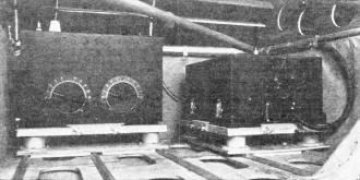
Figure 3 - Here are shown the Western Electric transmitter (left)
and receiver installed in a plane, ready for operation. Usually located in an out-of-the-way
corner, the receiver is tuned by remote control from the pilot's position. The remote
control cable is shown here, attached to the front of the receiver
Both the transmitter and the two receivers are mounted on trays which are constructed
in such a manner as to provide a high degree of shock absorption, thus guarding
against unduly severe mechanical strain due to vibration and landing shocks.
Usually both the transmitting and receiving equipment are located in some unused
portion of the plane's fuselage and therefore a remote-control tuning apparatus
is provided in the pilot's cockpit.
For itinerant aircraft a low-powered transmitter (Figure 3) has been developed
to meet the especial requirements of this branch of the flying service. This transmitter,
in design is much like that intended for the use of the transport planes, the difference
being that instead of having a fifty-watt carrier this one has only a ten-watt output.
The transmitter consists of a quartz crystal oscillator, a modulating amplifier
and one stage of audio-frequency amplification. The ten-watt output is substantially
completely modulated and the tuning range of the transmitter is from 3000 kc. to
6500 kc.
In the transmitter is contained an antenna transfer relay by means of which the
antenna may be connected to either the transmitter or the receiver. Power for the
operation of this transmitter is obtained from a dynamotor driven from the ship's
12-volt storage battery. It delivers 525 volts d.c.
As is to be expected, the ground station which is used to communicate with planes
operating in the transport service over the established chain airways is more elaborate
and more powerful than the plane equipment.
The ground transmitter produces a carrier power of 400 watts which as in the
case of the plane transmitter is substantially completely voice modulated. It is
so designed that it may be adjusted for operation on any frequency between 1500
and 6000 kilocycles.
This transmitter comprises the following units: a crystal-controlled oscillator,
a frequency doubler, a modulating amplifier an audio-frequency amplifier and a power
amplifier. In the oscillator and frequency-doubler stages five-watt tubes are employed,
while in the modulating amplifier stage a fifty-watt tube is used. The radio-frequency
power amplifier employs a single 1000-watt (1kw.) radiation cooled tube which operates
at a plate potential of 2500 volts. The audio amplifier system is similar to the
plane unit in that it uses three fifty-watt tubes connected in parallel and operated
by a special design of microphone.
The rectifier system works from a 220-volt three-phase 50 or 60 cycle line and
supplies potentials on the order of 2500, 1000, 200, and 55 volts d.c. and 10 volts
a.c. Rectification is obtained by means of seven low voltage mercury vapor rectifier
tubes.
At airports which are not on the regular chain airways and where there is the
desire to provide radio communication facilities to itinerant aircraft the ground
station is not nearly so elaborate. The Federal Radio Commission has stipulated
that such ground stations operate on a frequency of 278 kc., and that their carrier
output be restricted to 15 watts. Actually the transmitter described here is rated
at ten watts output. It consists of a crystal-controlled oscillator, a modulating
power amplifier, a speech power amplifier, a full-wave rectifier, filament supply
and all the necessary control circuits.
The purpose of such a transmitter is to provide communication to pilots on planes
in the vicinity of or nearing the airport so equipped. It is not intended for long
range communication.
The maps which accompany this paper will serve to illustrate that fact that a
pilot, whether he be of the itinerant or transport class and whose plane is equipped
with the prescribed radio apparatus, need never be out of touch with the ground,
regardless of whether he start out on a flight to a neighboring town or a more pretentious
transcontinental flight.
Every day flying becomes increasingly safer because radio provides the long arm
of communication as no other agency can, to keep the pilot informed of flying conditions
ahead, landing facilities at unfamiliar airports and the other thousand and one
things which only pilots want to know when they are out of touch with the rest of
civilization.
Posted April 17, 2023
(updated from original post
on 5/22/2014)
|


