|
|||||||||||||
 |
|||||||||||||
Dividing Networks |
|||||||||||||
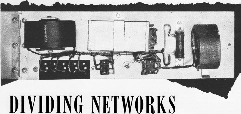
Dividing Networks By Harold Renne Technical Editor. Radio & Television News
This is an interior view of an RCA type of dividing network for theater use. The crossover frequency is 400 c.p.s. A two-speaker system using a tweeter and a woofer has many advantages over a single speaker system. Because of the difficulty in manufacturing a speaker with a single cone assembly which will satisfactorily reproduce both the extreme low and extreme high audio frequencies, it has become rather common practice to use a dual speaker system for high-quality installations. In such installations, a low-frequency speaker, or woofer, is used which is designed primarily to satisfactorily reproduce low frequencies, and a high frequency speaker, or tweeter, is used which is designed for the high frequencies. It is desirable in systems of this nature to "sort out" the low frequencies from the high frequencies and apply each to the proper speaker. A network for performing this function is called a dividing network, and the point at which the frequency division takes place is called the crossover frequency. This is the frequency at which the two speakers receive equal amounts of energy.
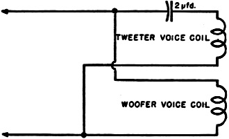
Fig. 1 - Schematic of a simple dividing network which will operate quite satisfactorily. Experience has indicated that a dividing network should have an attenuation beyond the crossover frequency of from 6 to 12 db. per octave. This may be accomplished with fairly simple networks. Two types of circuits may be used: the filter network and the constant-resistance network. Both have advantages and disadvantages, and both will be discussed. Fig. 2 shows parallel and series filter dividing networks, made up of half-section elements of the so-called m-derived type. Full section elements could be used, giving an attenuation of 18 db. per octave beyond the crossover frequency, but the slight improvement in operation is not worth the additional cost and losses involved. With extreme care in design, a dividing network may introduce as little as 0.5 db. power loss, but even this can become appreciable when high powers are involved. For example, at a power level of 100 watts, a 0.5 db. loss represents a power loss of about 11 watts. The equations in Fig. 2 indicate how the condenser and inductance values may be determined. The value of Ro indicates the impedance of each of the speakers and the input impedance to the network. The crossover frequency fc is determined by the speakers used and should be as low as possible. Each speaker should be able to contribute appreciably to the sound output at least one-half octave beyond the cross-over frequency. The filter-type dividing network is somewhat more versatile than the constant-resistance type and has slightly better transmission characteristics in both the transmission and attenuation bands. It does not lend itself readily to mass-production techniques, however, as two different values of inductance and capacity are required.
Some typical commercial dividing networks. (A) RCA network with 400 cycle crossover for theater use. (B) Brociner Electronics constant-resistance network with 500 cycle crossover and an attenuation of 12 db. per octave. (C) Circuit used by Stephens Mfg. Co. to give an attenuation of 12 db. per octave and a crossover of 600 cycles. (D) University Loudspeakers. Inc., network with 600 cycle crossover frequency. Both the parallel and series type of networks are effective, but listening tests seem to favor the series type (Fig. 2B). It might be instructive to calculate a typical dividing network on the basis of the circuit and equations given in Fig. 2. For the reasons given before, we will choose the series type for our calculations. A typical value for the speaker and input impedances would be 8 ohms, and the crossover frequency will be chosen as 800 cycles. Substituting these values in the proper equations gives the following constants for the network: L2 = 1.6 mhy. C3 = 40 μfd. L3 = 1.0 mhy. C1 = 25 μfd. The inductances should be wound with fairly heavy wire on a nonmagnetic coil form, such as wood. An inductance bridge is very helpful in obtaining the correct values. The coils should be mounted with their axes perpendicular to avoid mutual coupling. The condensers must not be of the electrolytic type, but they may be paper or oil-filled. Some condensers available on the surplus market would be suitable. Observers report that the calculated values of inductance and capacity may be varied as much as 25% without any appreciable effect on reproduction as judged by listening tests. The constant-resistance type of dividing network is shown in Fig. 3. It will be noted that for a given network, the values of the two inductances and the two condensers are the same, making this unit easier and cheaper to build on a production basis. When properly designed, this network is equally as effective as the filter type. It has the theoretical advantage of presenting a constant load to the source at all frequencies, but the wide variation in impedance of the voice coils with frequency tends to defeat this advantage. Either of the networks shown will give an attenuation of about 12 db. per octave beyond the crossover frequency and will introduce a power loss of between 0.5 and 1 db. An attenuation of 18 db. per octave may be obtained by the use of π or T sections instead of L sections, but such attenuation is not essential, and, as with the filter type, the additional power loss resulting from introducing the additional components more than outweighs any advantage that might be obtained.
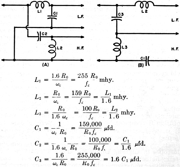
Fig. 2 - (A) Parallel and (B) series filter dividing networks made up of half-section elements. As an example of a typical series-type constant resistance dividing network (Fig. 3B) let us take the same conditions as before, namely, Ro = 8 ohms, fc = 800 cycles. This gives values for L2 of 1.1. mhy. and C2 of 31 μfd. A much simpler dividing network than those described above is frequently used. This network is shown in Fig. 1 and consists simply of a 2 μfd. condenser in series with the voice coil of the tweeter. The inductance of the woofer voice coil is appreciable, and its impedance rises with frequency. The inductance of the tweeter voice coil is relatively small, so the impedance of the condenser-voice-coil series combination decreases as the frequency increases. These two effects tend to cancel each other, giving a fairly constant impedance. In the above discussion, we have ignored the fact that the tweeter speaker is, in general, more efficient than the woofer. This would tend to give an unbalanced output with excessive high frequencies. For this reason, an attenuator is usually placed in the tweeter circuit to compensate for this increased efficiency. We have assumed in our dividing network calculations that the voice coil impedance of the tweeter and of the woofer were' the same. If such is not the case, the problem is considerably more complicated. If the tweeter voice coil impedance is higher, it may be shunted by a resistor, within limits, to bring the impedance down to the correct value. For example, if the woofer has an 8 ohm impedance and the tweeter is rated at 16 ohms, a 16 ohm resistor may be connected in parallel with the tweeter to bring the total impedance down to 8 ohms. Half of the high-frequency power is lost in this resistor, but the higher tweeter efficiency may make up for this loss.
Fig. 3 - (A) Parallel and (B) series constant resistance dividing networks made up of L sections. The above discussion has assumed that the dividing network is placed between the output transformer and the speakers. It is entirely possible to place this network in the center of the amplifier and then use separate power amplifier stages for the low and high frequencies. The network may be somewhat simplified since the value of Ro may be greatly increased and since power loss in the network is no longer a vital consideration. These advantages may be overcome by the additional cost and complexity of the two separate power amplifier channels, but this system has been used with marked success in a commercial amplifier manufactured in England. Another possibility is to place the dividing network in the plate circuit of the output stage, and then to use separate matching transformers for the high and low frequency speakers. This permits matching the network to any speaker impedance, and because the network is in a high impedance portion of the circuit, more convenient values of inductance and capacity are possible. At least one company using this latter system reports highly satisfactory results. With good woofer and tweeter speakers, proper enclosures, and a suitable dividing network, frequency response from 50 to 15,000 cycles can be readily achieved.
Posted February 15, 2023 |
|||||||||||||
 |
|||||||||||||
|
|||||||||||||


|
||||||||||||||||||||||||||||||||||||


