|
|||||||||||||
 |
|||||||||||||
Determining Voltage Standing-Wave Ratios |
|||||||||||||
Measuring voltage standing wave ratio (VSWR) is a fairly common and simple operation these days with readily available and relatively inexpensive test equipment. Inserting a power meter in series with a signal to measuring the incident and reflected power, or even simpler, inserting a bidirectional power coupler in series with the signal and measuring the difference between the forward and reverse ports is a routine matter for even modestly equipped laboratories, Ham shacks, or field operations. Simply plug the two values into the following equation for the answer: VSWR=(1 + β)/(1-β), where β=√(Prev/Pfwd). What if all you have is an oscilloscope, then how would you make the measurement? Actually, the calculation is even simpler because you use the ratio of the peak incident and reflected waves, but making the measurement requires more work. This article presents one way to get the job done. Comparison Methods for Determining Voltage Standing-Wave Ratios
Fig. 1 - Bench setup showing arrangement of transmission line for VHF work. Coaxial line is wrapped around box on the left. By J. F. Sterner Tube Department, Radio Corporation of America (RCA) A simple method for matching a load to a transmission line or for determining if a load is correctly matched. A combination of high-quality television test equipment such as a sweep generator, a high-gain oscilloscope, and a demodulator probe or detector provides a quick and accurate means for matching impedances, determining voltage standing-wave ratios, and measuring line attenuation. The technique described in this article is based on the observation and measurement of voltage standing-wave ratios to determine impedance matches. A good match between a component or circuit under test and a transmission line results in a VSWR approaching one. If the VSWR is not close to one, the circuit or component may be replaced by pure resistive loads having various values until the VSWR obtained with the original setup is duplicated; the impedance of the component or circuit may then be determined by direct measurement of the substitute resistive load.
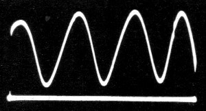
Fig. 2 - Pattern produced by shorted line.
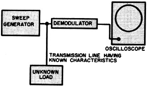
Fig. 3 - Test equipment arrangement for determining impedance match by VSWR.
Fig. 4 - Simplified block diagram shows the arrangement of test equipment for matching a transmission line to all antenna.
Fig. 5 - (A) Detector circuit for use with test equipment shown in Fig. 1. (B) A detector circuit for a balanced input.
Fig. 6 - Oscilloscope pattern produced by a 300-ohm line terminated by 330·ohm resistor.
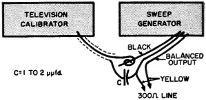
Fig. 7 - How a television calibrator is coupled to the input end of transmission line.
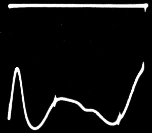
Fig. 8 - Tube loading effect across the antenna circuit of a TV tuner. The tuner presents a good match to the antenna over the passband as indicated by the two marks. This is the condition with the filaments turned on and "B+" applied to the circuit. The Comparison Method The complete physical arrangement of a suitable combination of test equipment is shown in Fig. 3. The output cable of the RCA WR-59C sweep generator is coupled to one end (input end) of the transmission line. The sweep generator must have good linearity and a constant output voltage over its frequency range. The input of an RCA WG-291 demodulator probe or a simple detector is connected to the same end of the line. The output of the demodulator or detector is fed to ·the vertical input terminals of the RCA WO-56A oscilloscope. The scope used in this method must have good linearity and good sensitivity. If the impedance of the load and the characteristic impedance of the line are equal, the voltage which appears across the demodulator or detector is independent of the frequency.1 In other words, if there is a perfect match between the load and the line, the voltage does not change as the generator sweeps through its frequency range. When the load impedance differs from the characteristic impedance of the line, however, the voltage across the detector or demodulator varies with a change in frequency. The amplitude of this variation is a function of the reflected voltage. If the line is shorted at the output end, highest impedance appears across the input end of the line at frequencies at which the length of the line is an odd number of quarter-wavelengths. At these frequencies, therefore, maximum voltage develops across the demodulator or detector. Lowest impedance and minimum voltage appear at frequencies at which the line is an even number of quarter-wavelengths. Fig. 2 shows a typical pattern which may be observed on the oscilloscope. The number of voltage peaks in the waveform is directly proportional to the frequency swing of the generator and the length of the line. This shorted-line method may be used to measure reflected voltage over a wide range of frequencies, provided that the vertical-amplifier gain control of the oscilloscope is adjusted initially so that the peak-to-peak amplitude of the waveform is equal to ten divisions on the screen of the scope. If the cable is then terminated by a load, the vertical distance between the maximum and minimum peaks of the waveform represents the reflected voltage. For example, a waveform having an amplitude of one division represents a reflected voltage equal to ten percent of the incident voltage over the range of frequencies covered. Attenuation in the line may also be measured, provided the sweep generator has blanking of the sweep oscillator so that a zero base line can be observed on the scope. If there are no losses in the line, the reflected wave equals the incident wave, and the voltage minimum is coincident with the zero base line. The distance from the zero base line to the voltage minimum therefore provides a measure of the attenuation due to losses in the line. Care must be used in this method to prevent the existence of any large degree of reactance at the short itself. To make an effective short for 300-ohm line, it is convenient to strip back the line about one-half inch and twist the leads together. For coaxial lines, it is better to strip back the inner polyethylene insulation about one-quarter inch and short the outside braid directly to the inner conductor. When measurements are made at VHF, the transmission line should be 75 to 100 feet long. 300-ohm line may be wound around a cardboard box, a packing carton, or any low-dielectric form. The spacing between the turns should be equal to or greater than the width of the line being used, as shown in Fig. 1. Coaxial cable may be placed in any convenient location without regard to spacing between turns. For most applications in which the frequency is below 216 megacycles, the detector or demodulator used in the measurements may be an RCA WG-291 demodulator probe or a simple detector such as that shown in Fig. 5A. An alternate detector for balanced input is shown in Fig. 5B. Either of these detectors may be constructed on a phenolic board 1/16-inch thick. The entire test setup may be checked by the connection of a 1/4-watt or 1/2-watt carbon resistor, having the same value as the line impedance, directly across the termination or output end of the line. The line connection to the resistor leads must be made in the area directly adjacent to the body of the resistor. The pattern observed on the screen of the oscilloscope should be similar to that shown in Fig. 6. It may be necessary to try several resistors having the same nominal value as the line before a good match is obtained because of variations in the resistance values and in the characteristic impedance of the line due to manufacturers' tolerances. When a good match has been obtained, the characteristic impedance of the line may be determined by measurement of the resistor. Use of Comparison Method The application of this method to the determination of impedance matches can best be illustrated by an example. If it is desired to determine the match of a 300-ohm transmission line to a television tuner, the tuner is connected as the load in the arrangement shown in Fig. 3. In this case, because the effect of the match is limited to a bandwidth of 4.5 megacycles, a television calibrator such as the RCA WR-39C is used in conjunction with the sweep generator and the oscilloscope. The calibrator is loosely coupled to the input end of the line. See Fig. 7. The sweep generator is set to the same frequency as the television tuner. Fig. 8 shows typical traces produced on the screen of the scope, representing a good match and a mismatch, respectively. The efficiency of the match may be determined from the standing-wave ratio, as follows: Efficiency = (VSWR-1)/(VSWR+1) where: VSWR = E2/E1 E2 = peak of reflected wave E1 = valley of reflected wave A similar arrangement may be used to determine the transformation ratio of a matching transformer. The primary of the transformer is connected as the load, and resistors are substituted across the secondary until a VSWR of unity is obtained. This arrangement is also useful in the matching of a transmission line to an antenna. In the case of a two-element array, for example, the sweep generator and demodulator are connected to the same end of the line as the receiver or transmitter, and the antenna is connected as the load. A good match is obtained by adjustment of the spacing between the two elements of the antenna to give a VSWR as close to unity as possible. See Fig. 4. The technique described in this article is simple, and the instruments are readily available. Accuracy of the method is within ten percent of that obtained using a slotted-line technique. The engineer or technician willing to spend the few minutes necessary to set up the equipment will find this method extremely useful.
Trace with the power removed from the tuner and the reactive components of the tuner circuit less tube grid loading causing a mismatch. This shows that the input transformer is properly designed for the type of tube used in this circuit, i.e., the grid circuit applies a resistive component across the antenna transformer so as to effect a good match from the 300-ohm input to the tube.
Reference 1. Bauer, John A.; "Special Applications of Ultra-High-Frequency Wide-Band Sweep Generators, "RCA Review, Sept. 1947
Posted February 10, 2021 |
|||||||||||||
 |
|||||||||||||
|
|||||||||||||


|
||||||||||||||||||||||||||||||||||||


