|
|
|||||||||
| Software: RF Cascade Workbook | RF Symbols for Office | RF Symbols & Stencils for Visio | Espresso Workbook | ||||||||||
|
|||||||||||||||||||||||||||||||
  |
   |
||||||||||||||||||||||||||||||
|
Please Support RF Cafe by purchasing my ridiculously low-priced products, all of which I created. RF & Electronics Symbols for Visio RF & Electronics Symbols for Office RF & Electronics Stencils for Visio T-Shirts, Mugs, Cups, Ball Caps, Mouse Pads These Are Available for Free |
|||||||||||||||||||||||||||||||


Electronic Component Checking (L, C, and R)
February 1957 Radio & Television News
| February 1957 Radio & TV News |
 [Table
of Contents] [Table
of Contents]
Wax nostalgic about and learn from the history of early electronics. See articles from Radio & Television News, published 1919-1959. All copyrights hereby acknowledged. |
When this article on component (resistor, capacitor, and inductor) measurement appeared in a 1957 issue of Radio& TV News magazine, readily available, inexpensive multimeters were not in existence. For about $20 you can now buy a brand new handheld DMM that will make very accurate resistance measurements and reasonably good capacitance measurements at frequencies up to a few MHz, where lead inductance starts to be significant (test frequency is usually only a few kHz). Finding an affordable, accurate inductance meter is another story. Cheap LCR meters can be purchased on Amazon for around $35-$50, and the quality is supposedly very good. For $150-$200, LCR meters are available the measure at multiple frequencies and display the complex impedance (real and imaginary parts). The most accurate measurement method uses a frequency in the realm of actual operation, and this article presents methods that will allow you to do just that by using typical bench top instruments.
Component Checking
 By N. H. Crowhurst
A discussion of various ways that circuit components in radio and audio equipment can be checked without trouble.
Sometimes the simpler things one encounters in radio and audio work are apt to get overlooked. For example, it would seem to be quite an easy matter to check the inductance of a smoothing choke or the capacitance of an electrolytic capacitor, with the correct polarizing current or voltage. However, when one looks around to find a test instrument to make the measurement, it just isn't readily available, so we are virtually forced into the routine of taking things for granted.
If we wish to check as to whether a certain component is functioning correctly or not, the only available method seems to be by substitution, using another component of the same type. Often this proves to be somewhat unsatisfactory, because the results can be inconclusive. We really need to know how to check the various fundamental components used in radio: resistance, inductance, and capacitance, to varying degrees of accuracy, ac-cording to their purpose.
Resistance Values
The simplest method of resistance checking is by means of a simple ohmmeter, either an instrument built specifically for this purpose or an ohmmeter range on a volt-ohm-milliammeter. Accuracy of this method of measuring resistance rarely exceeds 10% and may not even be as good as this.
Assuming that the accuracy of the moving coil meter used for the instrument is ±2% and that the resistors used in the instrument are accurate to ±1 %, the accuracy of the instrument as a perfect comparator between the internal and external resistances cannot be better than ±1%. And the accuracy of comparison is only to within ±2% of the full-scale current reading on the scale. If the scale reading, on a voltage or current scale, is compared with the reading on the ohms scale, it will be found that an error representing 2% of full scale in voltage or current reading may amount to an 8% error in resistance value. This is at the point of maximum accuracy of comparison, between the external resistance being measured and the internal resistance of the instrument.
Thus it is seen that the best accuracy obtainable using an instrument with a ±2% movement and ±1 % internal resistance gives a guaranteed accuracy at center scale reading of 9%. At readings between one-third and 3 times the resistance value, which is the range one might expect to use before switching to the next scale, the accuracy can reasonably be expected to stay within 10%. With an instrument using lower accuracy components than those used for illustration, the accuracy of the final reading in ohms will be considerably poorer than 10%.
From this it will be evident that an ohmmeter can only be used to make a rough check as to whether a resistance is within the preferred value range for which it is color coded - if it is of a ±10% or higher tolerance rating. To check that the resistance is within ±10% of its rated value, the result is a little doubtful and it is certainly impossible to rely on an ohmmeter reading to check to a tolerance of ±5% or closer.
Although the ohmmeter readings cannot be trusted for checking to close tolerances, it is possible to use an ohmmeter to check for reasonably good matching between pairs of resistors, if this happens to be the requirement rather than close precision in actual value.
As an example, in many push-pull amplifiers the resistors responsible for controlling the gain in the two halves of the push-pull arrangement must be closely matched to ensure balance. Production values may be specified to 5% or even closer tolerances, to avoid the necessity of having to select matched pairs, but the essential feature is that the value of the two corresponding resistors shall be within a close tolerance of one another. It will not necessarily matter if both of them are, say, 10% or 15% from their nominal rating, as long as they are within 5% of each other. This the ohmmeter is reasonably capable of checking, because it is quite possible to read an ohmmeter scale to within 5%. Since the question as to whether the reading is within 5% of its actual value is unimportant in this particular application, the significance of the reading does not matter as much as whether the two resistors which should be matched give readings within 5% of one another.
For some applications, however, such as calibrated attenuators or instruments for use in radio it is necessary to check resistor values to closer limits such as 5%, 2%, or even 1%, as the case may require. In these circumstances it is important that the value shall really be within the specified percentage of its rated value. The only method of making a measurement that is satisfactory for this purpose is to use a Wheatstone type bridge, using calibrated elements whose accuracy is better than the required component accuracy.
For most radio purposes the Leeds & Northrup bridge used for telephone line work is quite accurate enough. In using a bridge there are two things that control the accuracy of the reading obtained: (1) the accuracy of the resistance elements of the bridge itself, and careful attention to see, that contact resistance does not contribute an appreciable fraction under any circumstances; and (2) the sensitivity of the null detector.
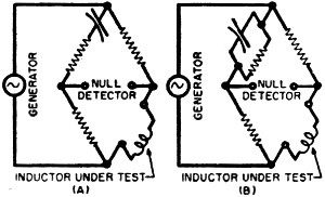
Fig. 1 - Bridge configurations for measuring inductance. (A) the "Hay" bridge. (B) the "Maxwell" bridge. Relative advantages of each type are discussed in the article.
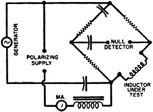
Fig. 2 - Modification of the "Hay" bridge to enable it to measure inductance with polarizing current flowing. Care is necessary not to exceed the dissipation rating of the various bridge elements. See text.
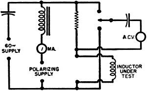
Fig. 3 - A simple inductance checker circuit for determining inductance with the polarizing current flowing in the component.
This second cause of inaccurate results can be checked by unbalancing the bridge by a known percentage to see that an adequate off-balance reading is obtained. Suppose, for example, the value required is 120,000 ohms, ±5%. Having balanced the bridge and obtained a null at, say, 120,000 ohms, the resistance in the calibrated arm should be altered by 5%, which represents a change of 6000 ohms.
If clicking in 6000 ohms additional in the calibrated arm shows appreciable deflection, then the reading may be regarded as accurate; but if the addition of 6000 ohms does not produce noticeable deflection from balance on the null detector, the result is not reliable. To improve its reliability one can either use a larger battery voltage or source of supply to the bridge, or else get a more sensitive null indicator.
Before leaving this discussion of resistance values it should perhaps be emphasized that it is not wise to put absolute trust in the color coding on a resistor. Occasionally even the best resistor will be found incorrectly color coded. If the error happens to be in the third color of the code, then the discrepancy in resistance value will be a matter of shifting the decimal point which can be quite serious. Also with some sets of coding colors the difference between some of the colors is somewhat difficult to determine, especially after the component has aged. For example, orange and brown can get to look quite alike.
Usually the first and second colors in the code can be identified by the combination used, from the recognized preferred value range. If the first color is blue, representing 6, the second color will most likely be either red, representing 2, or gray, representing 8, because 62 and 68 are the preferred values in the 60 to 70 range. But there is no such ready clue as to the likely color of the third band: it could just as easily be brown or orange. Thus a resistor in which this color looks at all doubtful could be either 620 ohms or 62,000 ohms, which is a considerable difference!
This is where an ohmmeter check can easily determine which of the two values is correct.
Inductance
Turning now to various kinds of inductance: the measurement of components not intended for the passage of d.c. and without iron cores is a fairly simple matter, with the aid of a conventional inductance bridge. Using such a bridge, employing either the Hay or Maxwell configuration (see Fig. 1), the inductance can be measured at a frequency suitable for the purpose, with a method quite similar to the operation of a bridge for measuring resistance.
The principal difference is that two kinds of adjustment are usually necessary to achieve null, because of the necessity for balancing the bridge in both amplitude and phase. This enables the bridge to give a reading of both inductance value and "Q" or loss factor. Bridges of this type are clearly marked to indicate the correct setting of the controls for making each kind of measurement.
There is usually no difficulty in achieving a null with the air-core type of coil, but if the inductance employs any kind of core, the null may not be quite as definitive, because of the distortion of the injected test signal caused by the core. Also, if the generator signal itself has any appreciable harmonic content, a Hay bridge will never give a balance at both fundamental and harmonics at the same setting. On the other hand, with an inductance where the only loss is due to its resistance, such as occurs in an air-core coil, the Maxwell bridge will give a fairly satisfactory balance for both fundamental and the lower harmonic frequencies at the same setting.
When measuring an inductor that employs any kind of core to increase the permeability, the magnetizing current is liable to distort so the inductor itself will generate some harmonics not present in the input from the generator. When the bridge is balanced to the fundamental generator input, there will be a residual harmonic present at the null point, generated by the inductor itself.
This is a good reason for using ear-phones if the generator frequency is in the audio range. Otherwise an oscilloscope with amplifier may be used as a null detector. It is then possible, listening to the tone or looking at the trace, to determine when the fundamental is balanced and the residue consists of harmonics.
But the conventional type of bridge is only suitable for measuring inductances where there is no polarizing current. The usual variety of smoothing filter choke has to provide a specified inductance when polarizing current is flowing and the inductance in the absence of such polarizing current will be considerably higher than the rated inductance of the choke with polarizing current. Unfortunately there is no simple fixed relationship between these two values.
If the choke has been designed to provide its maximum inductance at the polarizing current for which it is designed, the air gap will be adjusted so that, at this value of polarizing current, either reduction or increase of the air gap would result in a reduction of inductance value. However, in the absence of polarizing current, increasing the air gap will always reduce inductance value, while reducing the air gap will always increase inductance value.
From this simple fact it is evident that measuring an inductance with no polarizing current flowing is no criterion of its performance with polarizing current. It can, of course, provide a check that the inductance is not completely missing, due to short-circuited turns, in which case the inductance might not even be adequate without polarizing current flowing. But the fact that the inductance may measure twice its required value with polarizing current is no evidence that the choke will give its rated value with polarizing current.
Fortunately, with filter chokes of this nature close tolerances are not too important. Usually a compliance with a minimum inductance value will suffice.
It is sometimes possible to use a modified Hay bridge, as shown at Fig. 2, to inject a polarizing current so as to measure the inductance with the polarizing current flowing. But this can be a dangerous procedure, because the polarizing current may exceed the wattage rating of some of the internal components of the bridge and cause permanent injury to it. It is, therefore, better to devise a simple checking arrangement, as shown schematically in Fig. 3.
This does not employ a bridge method, but checks the inductance by injecting a known frequency and comparing the a.c. voltage developed across the inductor with that across the resistor in series with it. The relation between the a.c. components of voltage developed will enable the approximate inductance value to be calculated. This does not take into account the effect of the inductor distorting the waveform of the a.c. signal component, which invariably occurs in this type of inductor and is, in fact, another reason why any attempt to produce a precise figure of inductance will be somewhat meaningless. A rough check of this nature is quite adequate for the purpose.
If 60 cycles is the supply frequency for the a.c. component, dividing the calculated impedance of the inductor by 377 will give the inductance value. For example, suppose the series resistor used is 100 ohms (carefully checked in value), and the a.c. voltages measured across the resistor and inductor are 2 and 30 volts, respectively: then the impedance of the inductor at 60 cycles is 1500 ohms, representing approximately 4 henrys.
Capacitance
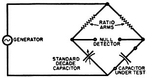
Fig. 4 - The "Drysdale" bridge which is used for measuring capacitance. Refer to text.
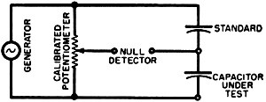
Fig. 5 - A simple bridge for capacitor checking that forms the basis of a number of commercial units on the market. The null detector is usually a "magic eye" tube.
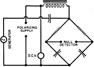
Fig. 6 - Modification of a "Drysdale" bridge to permit the measurement of electrolytic capacitors with polarizing voltage applied.
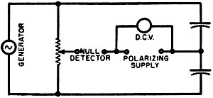
Fig. 7 - Modification of the simple bridge of Fig. 5 to enable polarizing voltage to be applied to the electrolytic capacitors.
For measuring all except electrolytic capacitors there are two methods, which correspond in relative accuracy with the ohmmeter and bridge methods used for measuring resistance.
The Drysdale bridge (see Fig. 4) is a modified Wheatstone bridge, in which resistance arms are used in the ratio positions, while a calibrated decade capacitor is substituted for the calibrated resistance in the variable standard arm. This type of instrument can give capacitance results comparable to those obtained with the Wheatstone or Leeds & Northrup bridge for resistance, but its use involves careful adjustment of a number of controls until a null is achieved.
The alternative method of capacitance measurement also uses a bridge, but one in which the null is much more quickly achieved. In this bridge (see Fig. 5) a standard capacitor is used in one arm, the unknown capacitor in another arm, and a single potentiometer-type resistance for the other two arms. This resistance is calibrated on the basis of the ratio between the unknown and standard capacitors necessary to achieve null.
With this type of bridge the unknown capacitor is connected across the terminals of the bridge and the one dial turned until null is indicated. The capacitance value is then read off the dial. The accuracy of this type of instrument is usually comparable to that of an ohmmeter, depending upon the accuracy with which the potentiometer type resistance has been calibrated.
Neither of these methods is really satisfactory for the measurement of electrolytics. This can better be understood by discussing a little further the behavior of electrolytic capacitors under different conditions.
In the first place, electrolytic capacitors freshly formed ready for use, have a dielectric film on the active plate of the correct thickness for the working voltage. Under this condition the capacitor should have its rated capacitance.
But if the capacitor is operated consistently at a lower polarizing voltage, the thickness of the formed film will gradually deteriorate with the result that the effective capacitance will increase somewhat. This is not necessarily detrimental to the performance of the capacitor, provided it is not subsequently required for service at its nominal working voltage.
In much the same way electrolytic capacitors kept in storage also show a deterioration in the dielectric film resulting in an increase in effective capacitance. This means if a six-month-old capacitor is taken from the shelf and measured on a regular capacitance bridge, without applying the necessary polarizing, it will probably show a value considerably in excess of its nominal value. However, it will not be satisfactory for operation until the electrolytic film has been formed up to the requisite thickness for its working voltage.
This will have to be done with the aid of a limiting resistor connected in series with the capacitor to limit the polarizing current while the film is forming. Only when the film has formed up so the voltage appearing across the capacitor is at its working value without excessive leakage current can its capacitance be measured to give a reliable indication of its operating condition.
Also, if the capacitor is to be installed in a piece of equipment for operation at its nominal working voltage, it is vital that this reforming of the capacitor be performed before installation, so the capacitor does not take an abnormally high leakage current when the power is switched on and possibly destroy itself before it has had a chance to become correctly reformed.
The correct measurement of electrolytic capacitors with polarizing voltage applied can be undertaken with either type of bridge, modified to a certain extent, as shown in the schematics of Figs. 6 and 7. If the actual capacitance value of an electrolytic capacitor is not vital, which often is the case, then all that is necessary in installing a new one is to ensure that it is correctly formed to its working voltage before connecting it in. This may be done with the aid of the circuit shown in Fig. 8, which consists of a high resistance feeding the capacitor with a voltmeter across it to indicate when working voltage has been reached. The resistor limits the leakage current through the capacitor to well within the maximum leakage current allowed, and when the capacitor has reached its nominal charged voltage, it can then be removed from the charging arrangement. Then, after discharging the capacitor for the sake of safety, the capacitor is ready for installation in its intended circuit. Discharge should preferably be accomplished through a fairly large resistor. The common practice of short-circuiting a fully charged capacitor results in a very high discharge current that may damage the capacitor.
Sometimes a capacitor which has been in stock a long time will deteriorate in the quantity of electrolyte present, so the capacitance will fall low in value, even after it has been adequately reformed.

Fig. 8 - Details for constructing a simple jig for forming electrolytic capacitors up to their working voltage.
If it is not convenient to build a capacitance measuring arrangement incorporating the polarizing supply, a fairly legitimate result can usually be achieved by ensuring that the capacitor is correctly formed using the polarizing jig of Fig. 8, then discharging the capacitor and finally measuring it immediately with the aid of one of the conventional capacitance bridges without polarizing voltage.
If the electrolytic capacitor is reasonably stable, a null will be obtained which will not vary at a perceptible rate. If the capacitor is not sufficiently stable to be reliable in use, the null may be observed to vary perceptibly while the measurement is being taken. If the capacitance varies at a rate that can be noticed while making the measurement, then the capacitor should be discarded as insufficiently stable for reliable operation.
The foregoing discussion has covered the more common measurements necessary on resistance, inductance, and capacitance. Sometimes much more precise methods of measurement are necessary, especially where the equipment is for some kind of standard operation such as a precision oscillator. In this kind of application it is often necessary to make measurements, not only as to the precise value at room or ambient temperature, but to determine the effect of temperature on the component. To make such measurements, only precision bridge apparatus is satisfactory, and the component should be measured under carefully controlled conditions of temperature and the measurements repeated at different temperatures, to discover what temperature coefficient the component possesses. Fig. 8. Details for constructing a simple jig for forming electrolytic capacitors up to their working voltage. See article.

Copyright: 1996 - 2026 |
About RF Cafe RF Cafe began life in 1996 as "RF Tools" in an AOL screen name web space totaling 2 MB. Its primary purpose was to provide me with ready access to commonly needed formulas and reference material while performing my work as an RF system and circuit design engineer. The World Wide Web (Internet) was largely an unknown entity at the time and bandwidth was a scarce commodity. Dial-up modems blazed along at 14.4 kbps while tying up your telephone line, and a lady's voice announced "You've Got Mail" when a new message arrived... |
Copyright 1996 - 2026 All trademarks, copyrights, patents, and other rights of ownership to images
and text used on the RF Cafe website are hereby acknowledge My Hobby Website: My Daughter's Website: |
