|
|||||||||||||
 |
|||||||||||||
Vibrating-Wire Audio Filter and Oscillator
|
|||||||||||||
Here is an interesting article titled "Vibrating-Wire Audio Filter and Oscillator," that appeared in a 1968 issue or Radio Electronics magazine. Author John Rankin describes a very high-Q (i.e., narrow bandwidth) bandpass filter operating in the audio frequency band that uses a length of taut wire suspended between the poles of a horseshoe magnet. He was able to obtain bandwidths as narrow as a couple Hertz. The useful frequency range proved to be from near 0 through about 20 kHz. Of course the experimental setup used was probably not endure in a normal operational environment, the principle demonstrated is quite interesting. It might be considered a mechanical analog to something like a microwave-frequency magnetron whose resonant frequency is determined by electrons in a cavity surrounded by a magnet. I have mentioned in the past about how early (1950s) radio-control system receivers for model airplanes employed a series of resonant vibrating metal strips (aka reeds) to demodulate signals from the transmitter. Vibrating-Wire Audio Filter and Oscillator
Novel amplifier circuit has an exceptionally narrow bandpass of only 1 or 2 Hz. By John C. Rankin If a straight piece of wire is placed in a magnetic field and an audio - frequency voltage is applied to it, the wire will vibrate and act as a very narrow bandpass filter. Wire Filter Figure 1 shows a 2-inch length of No. 38 wire in a field supplied by a 2 oz. magnet. The wire resonates near 1000 Hz and behaves like a high-Q LC circuit. Most 1000-Hz circuits consisting of inductance and capacitance have low values of Q - between 5 and 10 - due to the high resistance of the large amount of wire required. Resistance and capacitance are often used in parallel-T circuits for better results. Although the curve of such circuits indicate good selectivity, close examination will nevertheless show that they rarely have a Q greater than 15. Sometimes regeneration is applied to both these circuits to improve selectivity, and at maximum selectivity the Q may reach 90 in a circuit bordering on instability. The selectivity of any of these circuits may be classed as poor and leaves a lot to be desired. The vibrating wire in Fig. 1 has a Q of over 600 near 1000 Hz. It can be one of the most selective audio amplifiers available for such uses as telemetry, communications (CW) or wave analyzers. The short vibrating wire is a low-impedance device. I used the bridge circuit of Fig. 2 as a bandpass amplifier. The bridge is balanced by feeding in any frequency except the resonant one of the wire, then adjusting R2 for a null. When a signal of about 1000 Hz is applied, the wire vibrates, its impedance changes and the bridge is no longer balanced; so the 1000-Hz signal is passed.
Fig. 1- Position of pole pieces and magnet is not critical, but the wire must be taut and not touch the pole pieces.
Vibrating wire in a bridge gives this amplifier an exceptionally narrow bandpass, making it ideal for remote control work.
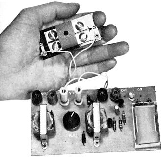
A prototype vibrating-wire sinewave oscillator. Its circuit is unique in that no L, C or R elements are used for tuning. Transformers T1 and T2 can be any type of speaker transformer used in tube or transistor radios and connected so that T1 steps down and T2 steps up. The transistor amplifier makes up for losses in the balancing network; gain from input to output is about 4. If the input is too high, the wire will vibrate excessively and will possibly touch the pole pieces. Under high input conditions, the vibrating wire will act as a frequency doubler and a 500-Hz signal will produce a 1000-Hz signal at the output terminals. If signal level is kept reasonably low, however, the device remains linear. Good operating conditions seem to be about 50 mV in and 200 mV out. Strong input signals can move the wire to the electrical center of the pole pieces, which may not be the position in which the wire was originally placed. This change in position alters the strain on the wire, varying the original frequency. You can avoid this by sealing the wire at both ends so that it cannot be moved at the end supports. Wire Oscillator The vibrating wire can also be used as an oscillator. The circuit of Fig. 3 oscillates at around 1000 Hz and is a bit unusual; there are no capacitors in the oscillator circuit, only in the power supply. Variable resistor R7 is adjusted for lowest output distortion when used with two types of wire to be described later. Distortion is 8% at 400 mV out and 3% at 100 mV. These figures probably could be improved, however, by using true complementary transistors and changing resistor values. Both transistors are high-gain types and should not be changed unless similar gain units are available. I constructed several of these oscillators; all performed well. Vibrating-Wire Construction The assembly consists of a General Company 2-oz. magnet placed on 2" x 1/2" iron mending plates made by National Manufacturing Company of Sterling, Ill. Both items are available in hardware stores. The mending plates are mounted with 1/4" bolts on a 3" x 1/2" piece of 1/16" plastic. I spaced the plates about 1/16" apart. The wire is stretched taut in the center of the gap and soldered to a 2-56 screw mounted at each end of the plastic. Run the wire through a hole at each end of the plastic before soldering it to the screws; then shim the plastic rod (.025" diameter) at each wire end. You can cut the thin plastic rod from a plastic whisk brush. As the heart of the device, the wire must be prepared carefully. Originally, I used No. 38 enameled copper wire; the enamel was removed with fine sandpaper. Then I noticed the resonant frequency changed in time, because the copper did not retain its original tautness. A 6" length was then stretched to 7" before installation - with improved results. At this stage I noticed something unusual: only half the length of wire had stretched - which meant the wire had two diameters - and the output of the amplifier had two adjacent peaks similar to two overcoupled coils.
Fig. 2- Resonant frequency of vibrating wire (VW) sets passband of this amplifier.
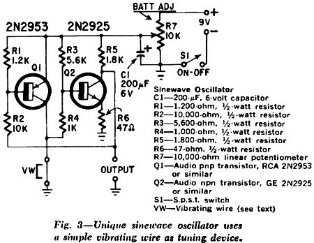
Fig. 3- Unique sinewave oscillator uses a simple vibrating wire as tuning device. My best results were obtained with a special nickel alloy wire. An assembly using this wire was subjected to heat and cold and proved very satisfactory. When it was frozen for 1 hour and immediately checked, the original frequency of 1000 Hz had changed to 960 Hz - only a 4% change. Since wire contracts with cold, the frequency should have increased; the lower frequency may have been due to moisture on the wire causing a change in its mass. Nevertheless, within 10 minutes the resonant frequency returned to 1000 Hz, although the unit was still very cold. Nickel alloy wire is easy to handle and solders easily; it is available in 24" lengths. For those who may wish to try it, it is called Nickel Alloy 180 with 0.004" diameter. You can order it from the manufacturer, California Fine Wire Co., 390 Manhattan St., Grover City, Calif. 93433. Cost is $1, including postage in the USA. Adjustment and Operation The value of resistor R1 in Fig. 2 depends on the type of wire used as the vibrator; if you use copper, R1 should be a piece of wire identical to that used as the vibrator. Nickel alloy has a resistance about 15 times greater than copper, so with nickel wire, you should use a 30-inch length of No. 38 copper wire, or a carbon resistor of 1 or 2 ohms, for R1. You will find the correct value when R2 nulls at about mid-range. Resonant frequency of the vibrating wire is varied, by changing the tension on the wire with a screw and threaded bushing. I made a unit that had a frequency variation of 750 Hz to 1500 Hz. You can use larger magnets, but oscillator output may be square waves, due to overdriving. In this case, it would be necessary to increase the value of R6 to possibly 150 ohms. An increase in magnet size means an increase in impedance of the vibrating wire, and in the amplifier this would mean an increase in output voltage. To test a vibrating-wire amplifier you need a good audio generator. Q is over 600, and I made this Q measurement by the 3-dB method; this means the bandwidth was 1.6 Hz at 1000 Hz Obviously, most audio generators cannot read this accurately. To make the measurements I constructed a generator with a 180° dial covering 10 Hz to 1000 Hz. Allowing for pointer width and dial markings, it was debatable whether the bandwidth was 1 Hz or 1.6 Hz - which actually puts the Q between 600 and 1000. Q is controlled by damping, and air causes damping of the vibrating wire -just as it does to a loudspeaker cone. Therefore, it's quite possible that even higher Q might be obtained by installing the wire in a vacuum. The frequency of the wire may be changed by changing its length or diameter or both. There is no low-frequency limit; units may be constructed for 60 or 120 Hz. The practical high-frequency limit seems to be in the vicinity of 20 kHz. I chose a bridge circuit for the selective amplifier because it is simple and easy to get operating. A bridge is not necessary, though; a differential amplifier - integrated circuit or otherwise - might well prove more satisfactory. Whichever way you try the vibrating wire, you'll find it quite different from the LC or RC circuits. |
|||||||||||||
 |
|||||||||||||
|
|||||||||||||


|
||||||||||||||||||||||||||||||||||||


