|
October 1960 Radio-Electronics
 [Table of Contents] [Table of Contents]
Wax nostalgic about and learn from the history of early electronics.
See articles from Radio-Electronics,
published 1930-1988. All copyrights hereby acknowledged.
|
The tunnel diode, with
its unique negative resistance region, excels as an oscillator and switch. As described
by Mr. Queen in this 1960 Radio-Electronics magazine article, is operating
bias is critical - typically around 0.2V for oscillation. The article details a
27-30 MHz crystal oscillator using a 1N653 diode, requiring precise voltage
division via a potentiometer (R1) and fine-tuning with R2. The load resistance must
be less than the diode’s negative resistance (-40 Ω). A 16-turn inductor and
adjustable capacitor (C2) optimize output. The circuit can self-oscillate without
a crystal but becomes unstable. For switching, the diode's characteristic curve
allows triggering via weak pulses or resistance changes. A light-sensitive version
uses a solar cell in series with a relay - illumination increases voltage, snapping
the circuit from a high-current (5 mA) to low-current (2 mA) state. Sensitivity
can be adjusted so even a 40 W lamp at 18 inches triggers the relay. Reversing
the solar cell's polarity enables triggering by interrupting light. The circuit’s
extreme sensitivity allows activation by nearby AC fields, like a soldering iron.
The Tunnel Diode Really Works
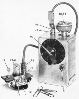
Simple tunnel-diode oscillator.
These two practical circuits
can be duplicated by the average experimenter
By I. Queen, Editorial Associate
The tunnel diode is an amazing semiconductor. Articles on it and its applications
have appeared in periodicals, but have often been too theoretical for readers who
like to experiment. Exact voltage and component values are often missing, making
it hard to duplicate the stated results. (The operating bias for a tunnel diode
is generally very critical.)
The July issue of
this magazine, page 26,carried an excellent discussion of basic principles of the
diode. It showed that this device has a negative resistance sandwiched between regions
of positive resistance. Fig. 1 shows a highly simplified form of the familiar tunnel
diode curve. Current increases as voltage is increased up to about 0.1 volt, then
decreases as voltage increases from 0.1 to a little less than 0.5 volt, when it
again starts to rise with increasing voltage. Voltage and current values are typical
for a 1N653 (Texas Instruments). Circuit theory indicates that such a device must
be an excellent oscillator and switch. This article will give full details on a
crystal oscillator for 27-30 mc and a switch that is triggered by light.
The Oscillator
The negative resistance region means that the tunnel diode is a ready oscillator,
As explained in the July issue, the load line must intersect the region of negative
resistance (Fig. 2). This load resistance is smaller than the negative resistance
of the diode, specified as -40 ohms for a 1N653. E1, the circuit voltage,
is a small fraction of a volt.
No battery with such low voltage is generally available, so a divider is needed.
Fig. 3 illustrates the crystal oscillator. Note the low value for R3 (which determines
circuit resistance). Oscillations occur when the voltage across the diode is about
0.2. Start with a 100-ohm pot for R1. To set it, vary R1 (and R2 for fine adjustment)
and listen for the signal on a nearby receiver tuned to the crystal frequency. Tune
C2 for maximum output. For 27-30 mc, L is 16 turns of No. 18 wire, 14-inch diameter,
close-wound.
You may also adjust this oscillator and observe circuit operation by measuring
voltages. Start with maximum resistance at R1 and R2, then raise the voltage across
the diode. (R2, the 20-ohm pot, is rather critical. Use 10 ohms for ease of control.)
At about 0.17 volt (as measured with a 20,000-ohms-per-volt meter) you will note
a sudden jump (to about 0.2 volt) and oscillations will begin.
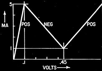
Fig. 1 - Tunnel diode characteristic in an idealized - or cubist
- form.
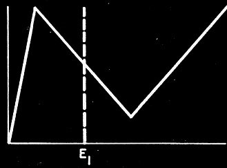
Fig. 2 - Operating point for tunnel diode oscillator.
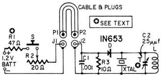
Fig. 3 - The tunnel-diode oscillator on the right; power supply
on the left.
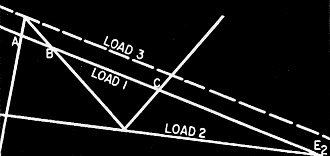
Fig. 4 - How the tunnel-diode characteristic is used in switching.
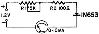
Fig. 5 - Tunnel-diode switching circuit.
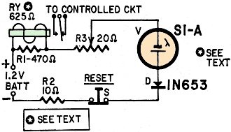
Fig. 6 - Practical tunnel-diode switch.
This circuit will work with any overtone crystal from 27 to 30 mc without retuning.
This is hardly the upper frequency range of a tunnel diode. With smaller tanks you
should have no trouble pushing the range higher. If you remove the crystal, the
circuit will self-oscillate with a rough and unstable signal.
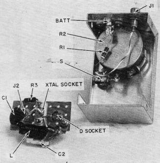
A look inside the oscillator.
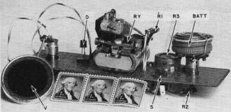
Switching circuit uses a tunnel diode.
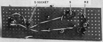
One resistor sits under the chassis of the switching circuit.
Once R1 has been determined for your particular diode and circuit, it may be
replaced with a fixed resistor. A 47-ohm unit is just right for my oscillator.
For safety, limit diode current to a maximum of about 6 ma till you determine
the current value for R1.
Construction is uncritical. In my unit, a battery and voltage-divider unit already
on hand was used. That portion of the circuit could, of course, be mounted on the
board with the other components.
Trigger Switch
When the load line intersects the diode characteristic in three places (as load
1 does in Fig. 4) we have a switch. As an example, suppose the circuit voltage is
E2 about 1.2 volts. Load line 1 resistance is about 250 ohms. When the
circuit is switched on, it stabilizes at point A.
Now if a weak positive pulse is applied to the diode, the operating point will
rise over the peak. It will move along the downward slope quickly (due to negative
resistance) and arrive at C. (Point B is an unstable position, and is of little
importance in this explanation). All this takes place instantaneously. Thus even
a very weak pulse will trigger the circuit from A to C. In a 1N653 these points
correspond to about 5 and 2 ma, respectively. (This is terrific amplification, if
you want to look at it that way.)
The triggering push may be an externally applied voltage or it may be just a
reduction in circuit resistance. To show this, refer to Fig. 5. Starting with maximum
R1, lower the resistance. At about 5 ma the meter will suddenly deflect downward
to 2 ma, although we are reducing R1. The operating point (Fig. 4) has moved up
the curve till it reached the peak of the characteristic. At that instant (when
it reaches the peak) it snaps to C. R2 (Fig. 5) is a limiting resistor.
Now increase R1. The slope of the load line becomes more horizontal until it
coincides with load 2, at which instant the current will snap upward. For the 1N653
this occurs when the total series resistance is about 1,250 ohms. The current will
snap from a low of 0.6 ma to 1.2 ma.
The circuit may be triggered by light falling on a photocell (Fig. 6). A low-resistance
Hoffman S1-A solar cell is shown in series with the winding of a relay RY to be
energized. Light falling on the solar cell increases the circuit voltage and triggers
the circuit. The higher voltage corresponds to changing the load line from 2 to
3 (Fig. 4). When the new line touches the peak point on the characteristic, the
circuit triggers and the relay drops out.
The photo shows an actual switching circuit based on the above experiment. The
relay must have a low-resistance winding. Being unable to find a suitable unit,
I modified a Sigma 5F-1000, which has two coils in series, for a total of 1,000
ohms. They are reconnected in parallel. to cut resistance to 250 ohms. Observe polarity
of windings. The yellow lead of each coil is soldered to the black of the other.
A 470-ohm resistor is shunted across the windings. This lowers the resistance and
the sensitivity of the relay. Now the relay should be adjusted to pull in at 4.6
ma, release at 2.3 ma, approximately. Prime the circuit by pressing the RESET button,
then lower R3 gradually until you are just below the trigger point. If triggering
occurs, note the point and start over again, this time not advancing the control
so far.
When properly set, the illumination from a 40-watt lamp at about 18 inches is
sufficient to trigger the circuit and release the relay. Note that the solar cell
is in series aiding with the battery.
This circuit may be made so sensitive that it can be triggered by switching on
or off a nearby soldering iron or other appliance. The magnetic field of the ac
does it.
If you reverse the polarity of the solar cell, you can prime the circuit with
illumination on the cell. Then you can trigger the circuit by interrupting the light
falling on the cell, even for a brief instant.
|


