|
|||||||||||||
 |
|||||||||||||
Lowdown on Traveling-Wave Tubes
|
|||||||||||||
Tom Jaski's 1959 article in Radio-Electronics magazine explains how traveling-wave tubes (TWTs) solve the critical transit-time problem in amplifying signals above 1,000 MHz (i.e., 1 GHz). Conventional vacuum tubes fail at these frequencies because electron movement becomes too slow relative to signal cycles, causing phase shifts and reduced amplification. TWTs cleverly use this slow electron transit to their advantage. A helical delay line slows incoming waves to match electron beam velocity. The wave's electrostatic field bunches electrons, which then transfer energy back to the wave in the retarding field phase, resulting in amplification. Magnetic focusing maintains beam integrity. With gains up to 70 dB and tunable operation across wide frequency bands (up to 25,000 MHz), TWTs became essential for microwave communications, radar, and military systems where high-power, efficient amplification was previously impossible. Lowdown on Traveling-Wave Tubes
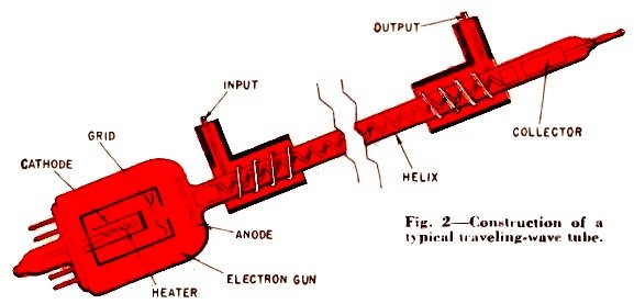
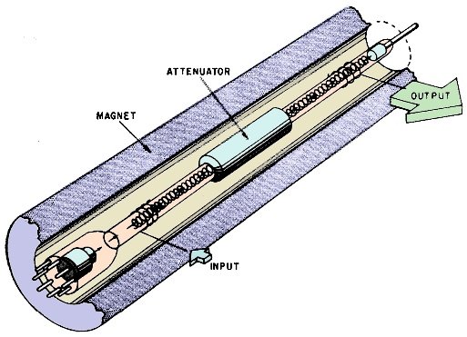
Fig. 2 - Construction of a ANODE typical traveling-wave tube. Travelling-wave tubes which can reach beyond 25,000 mc efficiently spell increased power and range for SHF communications. Here's how these "unusual" devices operate. By Tom Jaski One of the most difficult tasks in electronics is amplifying rf voltages above 1,000 mc. Yet here we find the most important and versatile applications of communications, long-distance remote control and military defense measures. Special tubes with very closely spaced electrodes, such as the lighthouse and pencil triodes, solve some of the problems up to 3,000 mc. Above this, on the transmitting end we just oscillate up a storm with bigger and better klystrons and magnetrons, and on the receiving end we heterodyne the feeble signals with a local oscillator and use a lot of if amplification. The disadvantages of such a system are obvious. We depend on the brute force of a signal which can easily be interrupted by interfering conditions and distorted by noise, or we have to make the transmitting range so small that we can hardly miss. Traveling-wave tubes offer a new approach to the problem. How they do this is what this story is about. But to understand the tubes, we must first understand the problem we are dealing with.
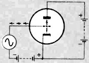
Fig. 1 - With an increasing signal there are more electrons between the grid and cathode.
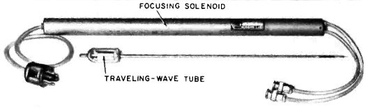
Fig. 3 - Typical traveling-wave tube and the solenoid used for focusing.
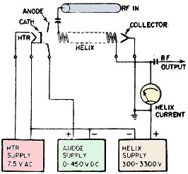
Fig. 4 - The circuits needed to operate a traveling-wave tube.
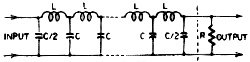
Fig. 5 - Typical delay line with lumped components.
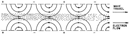
Fig. 6 - The field pattern of the traveling wave at any one instant.
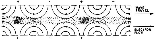
Fig. 7 - The field interacts with the electron stream, bunching the electrons.
Fig. 8 - Simplified diagram showing the tube mounted in its focusing solenoid. The attenuator helps keep reflected energy from traveling back down the tube in shf amplifiers.
Fig. 9 - In early models coupling to the helix was made by waveguide sections.
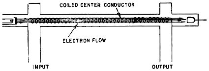
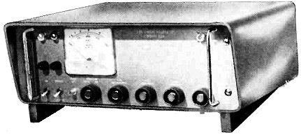
Fig. 10 - One of a series of signal generators made by Wave Particle Corp. The individual units cover the 500-15,000 mc spectrum in a series of 2-to-1 frequency bands : 500-1,000, 1,000-2,000 mc, etc. Transit-Time Problem The core of the trouble is transit time. It takes electrons a finite time to travel from the cathode to the plate. In the tubes in your radio or television receiver the transit time is about .001 µsec. One millimicrosecond (1 mµsec) doesn't seem like a lot of time and at broadcast frequencies it isn't. At 1 mc the transit time is just 1 /1,000 cycle. But at 1,000 mc, this would be as long as a whole cycle. The ordinary tube would long ago have ceased amplifying. Let's see why. Fig. 1 helps explain the situation. Here we have a triode with a negative grid bias. As we apply an input signal, the grid becomes less and less negative on the positive swing of the signal. Because of this the number of electrons in the stream from the cathode becomes greater, and we find a much denser electron population between grid and cathode than between grid and plate, because a number of the electrons haven't had time to get through the grid to the plate side yet. Because more charges (electrons) are approaching the grid than are leaving, the approaching mass of electrons, slowed down by the grid (still negative with respect to the cathode), imparts energy to it actually does work in repelling electrons from the grid out into the external grid circuit. When the input signal passes its positive peak and start to decrease, more electrons will be between the grid and plate-leaving the grid - and electrons flow back into the grid from the external circuit. When the signal reaches a negative maximum, this capacitive grid current reverses itself, reaching zero well before the voltage. In other words, we have a phase shift. The grid current leads the signal voltage, and we have a capacitive reactance in the grid circuit. Now, you know that the higher the frequency the lower the capacitive reactance becomes, so the tube draws current from the input circuit, loads it and lowers the input signal because of lowered grid - circuit impedance. The phase shift is proportional to the frequency and the transit time. Second, we can regard the tube's dynamic plate resistance as a complex quantity, made up of the resistive characteristics of the electron stream and the interelectrode capacitance in series. This, too, decreases plate resistance at higher frequencies. The lowered grid impedance lowers the transconductance. The amplification of the tube is the product of the transconductance and the plate resistance. Thus the amplification of the tube is very drastically reduced at these higher frequencies. This then is the transit-time problem - how to increase amplification which has been reduced because the electrons are slow. All the foregoing is pertinent to our discussion of traveling-wave tubes. For they are a good practical example of the proverb "If you can't lick them, join them." Instead of fighting transit time in traveling-wave tubes, we turn it to our advantage. First, let us look at the construction of the traveling-wave tube (TWT). Fig. 2 shows a schematic section of one (and in Fig. 3 you can see what it looks like). At the left is an electron gun, similar to the type used in cathode-ray tubes, which is capable of producing a collimated beam of electrons in the order of 1/8 inch in diameter. The anode serves the usual purpose of accelerating the electrons. Then comes a long thin glass tube with a wire helix inside. The helix may have as many as 50 turns per inch. At the far right is the connection to the helix, and at two points on the tube we see a spiral wound outside the glass. Then, finally, at the far right there is a positive collecting electrode. Typically the whole assembly is about 12 to 15 inches long (although much shorter tubes are being made experimentally) and the helix is about 9 inches long. The diameter of the helix should be about 11/64 inch and the glass tube around it somewhat under 3/8 inch. The electron gun is not very special, except for the shape of the beam, which is of uniform thickness. Fig. 4 shows the connections to the tube's elements. There is a heater supply, an anode sup- ply and a variable high -voltage supply for the helix. Then there are the input and output connections which, as we see, are made by the spiral around the glass and not by direct connection to anything. How It Works We talked about transit time, and we know that the electrons take a certain finite time to travel from the cathode to the collector electrode. To make use of the ability of this electron beam to impart energy to a wave, we must try to make a wave travel at about the same speed as the electrons. This is the purpose of the helix. The next logical question is, "How does the helix work?" Let's assume for the moment that we manage to introduce a wave on the helix from the input spiral. (How this is done is explained later.) A wave normally travels through space or along a path in a waveguide or, in the simplest terms, along a wire, with about the speed of light. But if we wind the wire into a helix, we create capacitance between the turns, and the turns themselves are in effect inductances. Now if you know what a conventional delay line consisting of series inductances and parallel capacitors looks like (see Fig. 5) , you can see the analogy between the helix and the delay line. In fact, the helix is enough of a delay line to slow the wave down by a factor of maybe as much as 30. As the slowed-down wave travels the length of the tube, we shoot the electron stream down through the center of it. Now what happens? The wave has both an electrostatic and a magnetic component. The magnetic component isn't useful to us. In fact all it does is try to scatter the electrons and break up our nice tight stream. However, we counteract this effect. The electrostatic component is what we use. We represent the instantaneous pattern of the field due to the wave in the tube as in Fig. 6, where the arrows indicate (by convention) the acceleration in a positive direction (the field will try to accelerate positive charges in the direction of the arrows, and electrons - which are negative charges -in the opposite direction). Thus some electrons will be speeded up and some slowed down, under the influence of the wave, and the beam of electrons will alternately be made denser and less dense (Fig. 7), depending on which part of the wave they are nearest to (whether they are moving toward a more positive or more negative area). We have produced bunches of electrons all along the beam. By changing the relative collector voltage we can change also the average speed of the electrons, and by choosing our velocities just right we can assure that the bunches of electrons we form with the wave field are either always in a retarding or an accelerating field. (Arrows pointing to the left accelerate, and to the right retard, electrons moving along the tube from left to right.) If we retard an electron (or anything else), we make it give up some of its kinetic energy. This energy must go somewhere, for it cannot be lost. In our case the energy is imparted to the wave, which then becomes a little stronger each time a bunch of electrons gives it some energy. To do this we make sure that our bunches are always in the retarding part of the field (in Fig. 7, area where the arrows point to the right). Thus, the wave we put in comes out with much more energy - it has been amplified. To counteract the magnetic component which tends to scatter the electron beam we use a magnetic focusing field around the tube. This can be done with a solenoid (Fig. 8) or with a structure of permanent magnets spaced along the length of the tube. Input and Output Circuits What we have left to explain is how we get the wave on the helix in the first place, and how we get it out again with something which does not even touch the wire. To understand this, you must grasp how a waveguide can be energized by a simple stub antenna (or simply accept the fact) . Actually the development of waveguides followed the use of coaxial lines, and a waveguide can be regarded as a coaxial line with the center conductor removed except at the very ends, where for purposes of putting the energy into the guide and taking it out we have left the center conductor, or something which acts like a center conductor. This can take many forms, and it need not be parallel to the walls of the wave-guide. In early traveling-wave tubes, input and output were handled by a short section of waveguide (see Fig. 9) which had to surround the helix for a short section. The helix was then functioning as the abbreviated center conductor. However, as the development of wave-guides progressed (delivering such new concepts as the G-string and the flat printed-circuit guides), the builders of TWT's understood that an actual conventional waveguide section was not required and that a simple wire wrapped around the glass would be just as good. Essentially, this is the idea of how we get the wave in and out of the helix with the simple outside spiral. The electrons' velocity in their long journey through the helix has to be very high if they are to reach the collector electrode. By putting a high voltage on the helix, we have some control over this velocity. So by controlling the helix (and collector) voltage we can make the tube suitable for waves which travel at different speeds. Since a delay line acts differently upon voltages of different frequencies, in effect we have a tube which we can use for various frequencies. Actually the traveling-wave tube is a wide -band device, but it need not always be. If we make the tube too efficient, we may end up with a very-narrow-band tube. Here's why. If we take out the wave from the helix, say in a waveguide fashion, the waveguide in turn can reflect energy into the helix. With the reflected wave traveling backward in the tube, the efficiency will be lowered a bit. However if the reflected wave reaches the other end at all, it will again be reflected, now forward, and will then be in the right phase for amplification. The amplified, twice-reflected wave will be added to the original, and so we have positive feedback and oscillation. Tubes designed for amplification only are so designed that the reflected portion never reaches the front end again. This is done by building losses into the helix or placing an attenuator consisting of a split graphite cylinder around it. Tubes made for oscillators use the reflection. But with the helix voltage constant, this tube will oscillate only in a narrow band of frequencies, no matter what we do to the rest of the circuit. Thus we have the apparent contradiction that we have a narrow-band device, which can be swept (by changing the helix voltage) over its possible range (of narrow bands). Some readers might have difficulties visualizing a "traveling" wave when there isn't anything really moving, like particles or such. I found it useful to think of a childhood game played with a rope. If you lay the rope on the ground and vigorously wag one end up and down, the whole rope will soon be in motion, although not running away from you. Progressively the "bulges" in the rope will seem to travel forward. These traveling "bulges" illustrate the idea of a traveling wave. It isn't going any place, it's just an amplitude which appears in different places. If a rope (or, better, a violin string) is wagged hard enough, particularly when it is stretched, you get the opposite or "standing" wave, which shows the same amplitude in the same place and seems to have a "bulge" which stands still. And before we forget, the backward "traveling" energy in the oscillator tube does of course cancel, in its first reflection down the tube, some of the effect of the first "forward" wave, but it is only a small percentage and more than made up for by the amplified second reflected "forward" wave. We take a portion of the output, manage to get some of it back down the tube, and amplify this to add to the original output, and we take a portion of the now bigger output and send it back down the tube, etc., etc. To put it in simple terms, that's how it oscillates. What Can They Do? Traveling -wave tubes can have a gain of as much as 70 db. By helix voltage control, TWT oscillators can be made to oscillate over a range of 2 to 1. Thus some tubes are available which will cover the band from 1,000 to 2,000 me and so on all the way up to tubes which reach over 25,000 megacycles. This is not necessarily the limit of TWT's; we just haven't much practical application for higher frequencies, yet. At present, the practical applications for TWT's are enough to keep the manufacturers quite busy. They are used first as broad-band, low-noise radio-frequency amplifiers. They are used as tunable oscillators. Fig. 10 shows a signal generator using a TWT as oscillator. Because of a feature which we haven't. discussed (the "grid" shown in Fig. 2, which can turn the electron beam on and off or modulate the electron stream, thus controlling its density and its ability to impart energy to the wave) we can amplitude-modulate the output. This "grid," which is really more like a "gate," operates like the grid of a cathode-ray tube for beam modulation. Therefore, TWT's can also be used as modulators at microwave frequencies. Telemetering, missile guidance, microwave voice communication, television program relays are present applications for the tubes. Scatter propagation, cable amplifiers for coaxial lines and radar systems are possible future applications. You can be sure that they will be playing an important part, for right now they are the only high-gain voltage amplifiers available for the microwave regions. |
|||||||||||||
 |
|||||||||||||
|
|||||||||||||

|
||||||||||||||||||||||||||||||||||||


