|
|||||||||||||
 |
|||||||||||||
Nuvistor - A New Kind of Electronic Tube
|
|||||||||||||
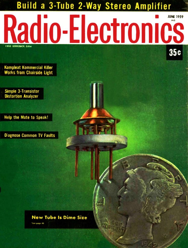
In 1959, RCA introduced the nuvistor, a vacuum tube featuring a metal-ceramic envelope, cantilevered cylindrical electrodes, and fully automated brazed construction. Designed for shock resistance, low power consumption, and miniaturization, it offered improved gain and noise figures over conventional tubes, with applications ranging from TV tuners to military equipment. RCA positioned the nuvistor as a superior alternative to transistors, highlighting its tolerance for overloads, looser manufacturing tolerances, and moderate voltage requirements. Despite these advantages and initial optimism that it would prolong the vacuum tube era, the nuvistor ultimately failed to halt the transistor's advance. Solid-state technology rapidly outperformed it in efficiency, cost, and miniaturization, rendering the nuvistor a short-lived, albeit innovative, footnote in electronics history. Nuvistor - A New Kind of Electronic Tube
New construction technique leads to the nuvistor, a vacuum tube that can compete with transistors. By Larry Steckler, Associate Editor A standard electron tube with some new twists - the nuvistor - is expected to last longer and do a better job, while using less power. The glass envelope is replaced by a metal ceramic envelope. No mica supports are needed. It has no getter - doesn't need one. It lends itself to completely automated construction much more readily than a conventional receiving tube. In a TV tuner, it has operated satisfactorily with as little as 5 volts on its plate. Let's start with what the nuvistor is. It is simply a vacuum tube in a new envelope, put together in a new way, that has been developed by RCA. The electrode elements slip into place on a simple jig. All electrodes are cylindrical and fit into each other. They are supported only at the bottom, in cantilever fashion - a technique which eliminates the need for mica support discs or spacers. All electrodes are small, light cylinders, and the assembled unit can withstand a lot of shock (850 G's) and vibration (2 G's at 5 kc) because of its shape and low mass. Spacing between tube elements remains constant as spot-welding techniques used in the manufacture of standard tube types are eliminated. Spot welding is a source of residual strains that can twist tube elements. Its elimination reduces the possibility of shorts developing in the tube during operation. Eliminating spot welding also gets rid of a potential source of failure and an operation that requires a high degree of manual skill.
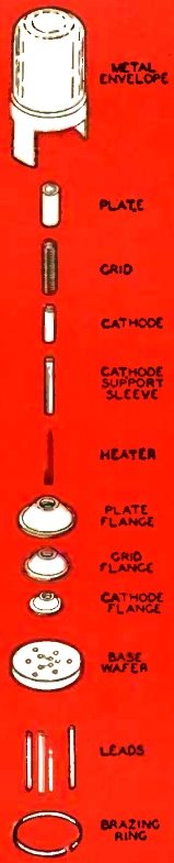
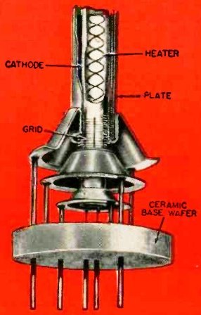
Fig. 1- Exploded view of the nuvistor triode. Assembly Technique The job of putting a nuvistor together is simple. You start with the parts shown in Fig. 1 to assemble a triode. An inexpensive jig is used to simplify and speed assembly. First the plate is slipped into place on the jig. The plate flange is placed over it. Next comes the grid and grid flange. (For greater detail, Fig. 2 shows some of the steps in assembling a large-scale model of the nuvistor triode.) The cathode support sleeve and flange follow. Now the heater is inserted in the base wafer and the heater-base-wafer assembly is slipped into position. All leads and support rods for the elements are dropped into their respective holes in the base wafer.
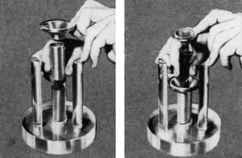
Fig. 2- Initial steps in the assembly of a nuvistor triode. An enlarged model is shown. hydrogen-filled oven. Flanged edges where they contact the tube elements and the leads have a thin copper coating. In the brazing oven (at a temperature of about 2,060°F), the copper melts and fuses the various connections. Fig. 3 shows the brazed assembly in detail. After brazing, the coated cathode is slipped over the cathode sleeve. The tube envelope, a metal shell, is placed over the internal element assembly and a final brazing ring is dropped into place. The unit is then placed in an evacuation oven. Air in the chamber is exhausted to a level equal to one-billionth of an atmosphere. Temperature in the chamber is about 1,600 °F. As this outgasses the tube at a high temperature (a glass envelope would melt), the tube can be operated at a temperature in excess of those permitted conventional types. The high temperature also makes the getter unnecessary. (The nuvistor has withstood tests in the temperature range from -320° to 660 °F.) After a suitable interval, the temperature is raised another 100° to about 1,700 °F. At this temperature, the brazing ring melts, fusing the shell to the ceramic base, forming a hermetic seal. Where to Use It Because of the nuvistor's high shock and vibration capabilities and low power consumption, smaller size and lighter weight, it will be especially useful in missiles, airborne, mobile and miniaturized equipment. However, it is also suited for portable radios, home and portable TV's and just about any other place a vacuum tube is used.
Fig. 3 - The brazed nuvistor assembly looks like this.
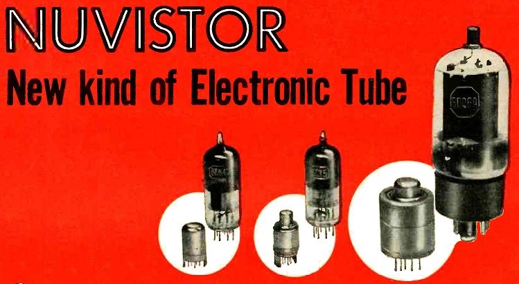
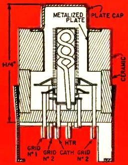
Fig. 4- Cutaway view of nuvistor beam-power amplifier. Triodes, tetrodes and beam-power types are in the works. Rectifiers, damper tubes and others are expected to follow. If the cold cathode (see "The Cold-Cathode Tube," Radio-Electronics, April, 1959, page 98) becomes practical, it can be incorporated to lower necessary operating power further. For a size comparison between nuvistors and the tubes they are intended to replace, see the head photo. Miniature vs. Nuvistor Let's take the triode first and compare it to the 6BN4-A, a vhf, TV r amplifier tube. Used for channel 13 (210 -216 mc), the nuvistor delivers about 3 db more gain and has from 0.5 to 1 db better noise figure. This places the nuvistor in the same category as available TV tuner tubes using frame grids. Other experimental triodes having 0.5-mil grid wire are about another 0.5 db quieter. For this operation, the nuvistor had 40 volts and 7.5 ma on its plate, about one-third the voltage and current required by a 6BN4. The table compares some of the characteristics of the two types. Nuvistor triodes also make excellent oscillators. Normal oscillator efficiency extends to 450 mc and oscillation is still strong above 1,000. To get an idea of tube efficiency, tests were run with a 435-mc oscillator. Oscillation started with 7 volts at the plate. With a 15-volt supply, plate current was 1.6 ma and a grid bias of -0.55 volt was developed across a 3,300-ohm grid resistor. A lower-mu version (mu = 20) starts oscillating at 2.5 volts and gives similar performance with 5 volts at its plate. The tetrode nuvistor follows a slightly different design. Its elements are assembled in the same manner, except that grid 2 is now where the triode plate would be located. The plate, connected to a metal cap, surrounds the cathode-grid assembly. The tetrode's walls are ceramic. Performance data indicate that the tetrode nuvistor is suitable for use in if and rf amplifiers of TV receivers. The 6.3-volt heater draws only 140 ma and, while used as a class-A amplifier, only 70 volts need be applied to the plate and 30 volts to the screen grid. Transconductance under these operating conditions is 9,000 mhos at a plate current of 5 ma. Beam-Power Version The tetrode just described is similar to the beam-power nuvistor (see Fig. 4). However, because of the tube's small size, heat dissipation becomes the major problem. Electrode areas in this size envelope are just too small for adequate heat radiation, so unique measures are required. The plate in the beam-power tube is a metallized surface bonded to the inside wall of a ceramic envelope. The ceramic conducts the heat from the plate to the outside of the tube. For additional heat dissipation, a heat sink, which could probably be the set's chassis, is needed. Research seems to indicate that it is feasible to use a nuvistor beam-power tetrode as the horizontal output tube in a color TV receiver. This tube, rated at 30 watts, would measure only 1 inch in diameter and 1% inches high. Such a tube would also have obvious applications in hi-fi amplifiers. As it would need a comparatively low-voltage supply, a rectifier connected directly to the line might do. Other calculations predict efficient performance to about 400 mc, so rf single class-C amplifier could handle about 100 watts (more with a special heat sink). Current drawn by the heater of such a tube at 6.3 volts would be approximately 800 ma, noticeably lower than the 1.2 amps of heater current drawn by the 6DQ6. As the tube could take up to 5,000 volts of peak-positive pulse plate voltage, it is extremely well suited for use as a horizontal output tube. Transistor Competitor RCA's nuvistor also provides new competition for the transistor. It is only a little larger than some types and, since heater current has been reduced, it becomes practical in portable equipment applications. Then, too, spacings in the tube can be 50 times greater than those in a transistor and still give comparable performance. This makes the tube a lot more economical, as tolerances are not as close or as difficult to meet, making rejects less likely. As the nuvistor operates at moderate voltages, components used in nuvistor devices are less expensive than those in ordinary tube circuits (higher voltage ratings make them larger and more expensive) or those in transistor circuits (high capacitances at low voltages call for expensive parts). Unlike a transistor, which will break down completely and irreparably as soon as any one of its maximum ratings is exceeded, the nuvistor is capable of handling momentary overloads, just like any other vacuum tube. In many amplifier circuits, the power required to run a nuvistor (heater, plate, grid current) scaled down to half of its present size can be reduced to 5% of that required by conventional miniature tubes. So while you may think that the transistor is putting an end to the vacuum tube, there is still a lot of tube life left. You'll be seeing vacuum tubes in your TV receiver for many years to come, although they may take on a new shape. Although the nuvistor is only in the early advanced development stage, samples are expected to be sent to equipment manufacturers by the end of the year and limited production is expected to be in progress by the middle of 1960. |
|||||||||||||
 |
|||||||||||||
|
|||||||||||||

|
||||||||||||||||||||||||||||||||||||


