|
|||||||||||||
 |
|||||||||||||
Circuit Boards Are Getting Better
|
|||||||||||||
This 1959 Radio-Electronics magazine article details a transitional phase in PCB technology, where manufacturers were responding to service technicians' concerns by implementing significant usability improvements. Key features included color-coded conductors for circuit tracing, board-edge connectors for easy removal, and "road-mapped" overlays replicating circuitry on the component side. Innovations like Westinghouse's "See-Matic" board functioned as a built-in schematic with component symbols printed directly on the conductor side. Boards were single or double-sided, utilized wax coatings and solder-resist layers, and emphasized serviceability through coordinate grids and test point identification. Today's PCB fabrication represents a quantum leap from 1959. Modern boards feature high-density interconnects with microvia technology, multilayer constructions exceeding 50 layers, and trace widths measured in microns. Automated optical inspection, surface-mount technology, and lead-free soldering have replaced manual servicing concerns. Advanced materials like FR-4 and polyimide substrates withstand higher temperatures, while computer-aided design allows for complex impedance-controlled routing unimaginable in the vacuum tube era. The evolution from servicing challenges to reliability engineering represents one of electronics' most dramatic technical transformations. Circuit Boards Are Getting Better
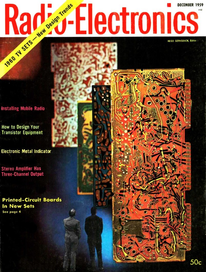
Top to bottom: Motorola, Westinghouse, Emerson, Philco, RCA. By Eric Leslie Representatives of a state federation of service technicians remarked last spring, after a conference with manufacturers: "Printed circuits are likely to be with us for some time, and we may have to learn to live with them." Fortunately, the very articulate reaction of the service field to certain features of these new components has made manufacturers examine their products from the points of view of serviceability, excellence of construction and reliability. Practically every 1960 TV set board has new features designed to make servicing quicker and easier. The four boards on this month's cover are by no means the only examples of such improvement.
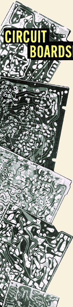
Solder in left top corner was applied with 250-watt gun, using plenty of time. Conductor at lower left was lifted only with considerable difficulty. The Motorola board used in their 17P6 portable is possibly the most interesting of the group on the cover (in the foreground). It is the only one of the four that has conductors on both sides. This has the advantage of permitting crossovers, thus making for straighter and simpler "wiring" patterns. The obvious disadvantage - difficulty in following circuit lines - is negated by using black lines to indicate conductors on the opposite side of the board. All conductors are color - coded to indicate their functions. A green line is immediately recognized as a grid circuit, for example, and a green line with red dots is a plate circuit. The type number of each tube is printed on the board and pin 1 indicated. All leads to other parts of the receiver are terminated in a row of contacts along one edge of the board. The whole board can then be clipped into a strip near the front of the receiver, making all contacts almost instantaneously. With the help of a special extension harness (or less conveniently, by disconnecting the strip, which has leads long enough to clear the chassis) the board can be connected into the circuit while standing up behind the set for more convenience in servicing. Philco Approach The Philco board, which appears just behind the Motorola on the cover, supplies a great deal of information to the technician. Tube type numbers and functions (6CG7, HOR OSC, 6DR7, VERT OUT) are both given, test points are indicated, and the lances that act as terminals and test points carry indications like "VERT HOLD, B+ 275, 2 AUDIO." Conductors are all on one side of the panel, and the underchassis pattern is reproduced in a distinctive pale blue on the component side.
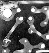
Motorola board functions while standing behind chassis for servicing.
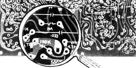
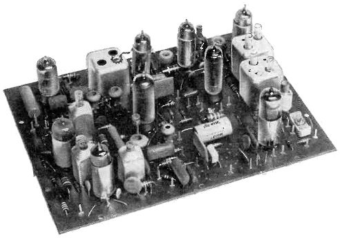
Magnified portion of a Westinghouse printed circuit board.
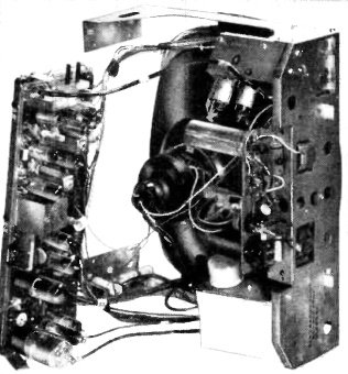
Top view of the Westinghouse. A large number of wire jumpers are visible. Security-Sealed Circuitry RCA refers to its board (third from front on the cover) as "road-mapped." All conductors are on one side of the board, and an exact replica of the wiring is carried on the other side in a white-dot pattern, as are all tube and component codes. The road-map feature is a system of locating components. The diagrammatic views of the board in the service data are divided into a grid by a series of letters on the sides and numbers on top and bottom. Thus a component whose coordinates are, for example, A5, can be located immediately. Terminals where leads leave the board are lettered, the same letters appearing at corresponding points on the schematic. Some of the earlier boards also had jumper wires between certain conductors. These were identified with double letters, one of which was J. Thus MJ on one part of the board is connected to MJ on another. The "security-sealing" refers to a coating of wax over the conductors, and to the firmness with which they are secured to the board. Emerson Board Some of the features of this board (shown at rear) seem intended to help the assembler as well as the service technician. Component and tube codes are given, and the codes so printed as to indicate the mounting holes for the components. If resistors or capacitors are long, lines are drawn from the lettering to the mounting holes. Outlines of some parts, such as coils or capacitors standing on end, are also drawn on the board. Some triangles, and circles, which looked rather important at first, are for use in assembly. While inquiring about these, it was brought out that new boards in the design stage at Emerson will carry a great deal more information, including voltages. This board is the only one that does not have the conductor pattern printed on the side of the board that has the component information. It is very translucent and obviously depends on the technique of using a light on the other side of the board to trace circuits. A Functioning Schematic The Westinghouse See-Matic board (not shown on the cover) has a number of interesting features. The component side of the board is absolutely blank - all lettering is on the conductor side. Since the conductors are right in sight, no circuit lines are necessary, and instead component symbols are drawn to show their position on the other side, with lines connecting to the proper conductors (see photo). The values of resistors and capacitors- rather than codes - are printed next to the symbols, together with pin type numbers and pin identification (G, P, K, etc.). Some components, such as coils and transformers, are identified by the component code near their symbols, and straight lines represent wire jumpers on the other side of the board. Test points are indicated by circled letters. The result is that each Westinghouse board is its own built-in schematic, and in many cases the technician can repair it without any additional service data. Some very useful features appear on the boards of other manufacturers not represented on the cover. In the G-E board, for example, ground-circuit conductors are indicated by the familiar triangular chassis symbol. Component codes and schematic symbols are both shown, and even the tubes are drawn in schematic style. Asterisked numbers refer to terminals at which leads go to components off the boards, and are of course duplicated on the schematic. Other Features The boards inspected showed a strong tendency to group components for simpler mounting. Numbers of Centralab Couplates, Erie Pacs and similar combinations were found. Boards are in most cases more rugged than earlier ones, and the conductors can be soldered with little danger of peeling them from their support. Even after a 250-watt Weller gun was held on one small conductor for a full 2 minutes, it could be loosened only with difficulty. Large amounts of solder were flowed onto other conductors with no loosening effect on the foil. Some of the boards have a wax layer over the conductors. It can be soldered through without difficulty. Practically all this year's boards have a solder-resist over all parts of the conductors except the portions where solder is desired. Thus solder is found only at points instead of covering the whole surface of the conductors. One aid not supplied by a set manufacturer is the Circuitrace feature of Sam's PhotoFacts. Important points on the conductor side of the board are pointed out with arrows terminating in black squares with white numbers. The same black squares and white numbers appear at corresponding points on the schematic, making it possible to locate up to 40 test points on some boards. A somewhat similar service is performed in the manufacturers' data on "road-mapped" sets, like the RCA, G -E and Emerson. Tables of important components with their coordinates are printed, enabling the technician to locate them rapidly. Another aid is RCA's 24-page booklet Printed Circuit Servicing Techniques. It describes general techniques, as well as the special features of a number of circuit boards, both of RCA and other manufacturers, and including both TV and radio circuitry. |
|||||||||||||
 |
|||||||||||||
|
|||||||||||||

|
||||||||||||||||||||||||||||||||||||


