|
August 1947 Radio-Craft
 [Table of Contents] [Table of Contents]
Wax nostalgic about and learn from the history of early electronics.
See articles from Radio-Craft,
published 1929 - 1953. All copyrights are hereby acknowledged.
|
We take a lot for granted these
days with the seemingly unlimited availability of cheap stuff of all kinds - some
of it complete junk and other of it pretty darn good. That goes for electronics
components and complete products and test equipment, tools, automobiles, appliances,
and utensils, clothing, medical equipment - you name it. Something as simple as
a pistol-type soldering gun can be purchased at just about any hardware or home
store, and at a price that when adjusted back to equivalent money in the 1940s would
be amazingly cheap even then. For instance a
Weller Soldering Gun kit from Lowes sells for $39.48 today (less when on sale),
which would have been $3.44 (per the
BLS Inflation Calculator) in 1947 when this article showing how to build your own appeared in
Radio-Craft magazine. If a soldering gun could have been purchased for a mere
$3.44 in 1947, there would have been no need to publish such an article because
its cheapness would have obviated any perceived need to build one from scrap parts that might
have cost about the same.
A Soldering Gun

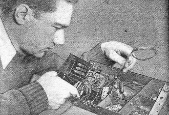
The author services a receiver with the aid of this soldering
gun.
By Ral Collins
The quick-heating soldering pistols now on the market are desired by many hams
and radio experimenters, but the cost is too high to warrant the purchase of one
by persons who do not use an iron a great deal. These are such handy little gadgets
that I undertook the construction of one from parts out of the ever-present junk
box. The first one I constructed is still giving good service after many hours of
operation.
Any small power transformer having a good primary will furnish the basic element
for this gun. The case is unbolted and the laminations carefully disassembled. All
windings except the primary are removed (the best way to remove the high-voltage
winding is to saw through it with a hacksaw). The number of turns in the 5-volt
rectifier winding is counted during the unwinding. This will serve as a guide to
the number of turns required by the new high current winding, which will be approximately
one-tenth of the number counted, for the new winding is to deliver about 0.5 volt
to an open circuit. A little experimenting with more or fewer turns might be necessary
to arrive at this potential.

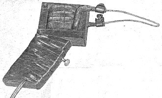
Appearance of the gun. Several modifications might be made to
suit it to the taste of the raw materials.
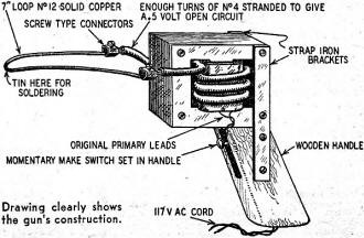
When the primary winding is free, the determined number of turns of No.4 stranded
synthetic covered wire is bent around it, secured, and the transformer structure
is reassembled as shown in the diagram. If sufficient space is not available in
the core structure to accommodate the covered No.4, the insulation is removed, and
a single layer of friction-tape insulation substituted.
A handle with a convenient switch is attached with 2 strap-iron or brass brackets,
and the primary connected to a line-cord through the switch and brought out through
the bottom of the handle. A 7-inch piece of No. 12 solid bare copper wire is bent
in a V and connected to the high-current leads with 2 screw-type connectors to provide
a simple and quick means of changing tips. Dip the point of the V in soldering paste,
push the switch, and in less than 10 seconds the point can be tinned and ready for
work.
The tool constructed in this way is not intended for assembly-line use, but will
in all probability serve to great advantage in the home workshop.

Posted May 4, 2020
|


