|
|||||||||||||
 |
|||||||||||||
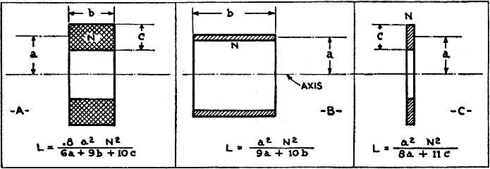
Simplified Coil Calculation
|
|||||||||||||
This might be one of the earliest printed instances of Harold A. Wheeler's simplified formulas for the three basic inductor forms. Wheeler is credited with having devised the first automatic volume control (AVC) using diode envelope detection. We all use them on a regular basis, but for most the origin was never known or has long since been forgotten (I fall into the latter category). I did some research on Wheeler's inductance formulas a few months ago while working on what is now titled "RF Cafe Espresso Engineering Workbook™," so it was sort of déjà vu when this blurb appeared in a 1932 edition of Radio-Craft magazine. Simplified Coil Calculation
Inductance Calculation Dimensions By G H. W. Nason The archaic method of calculating inductances involves a formula taking into account not only the actual dimensions of a winding and the number of turns of wire, but a form factor "K" dependent upon the ratio of length to diameter of the form on which the coil is wound. (See page 109, August 1931 issue.) While these formulas are no doubt, accurate to a minute degree in capable hands, the errors possible are manifold; and rarely, if ever, does a coil so designed come within a reasonable degree of the desired inductance. A considerable simplification of the design problem was evolved several years ago by Harold A. Wheeler of the Hazeltine Laboratories, who is responsible also for the multiplex detector and automatic volume control used by Philco, Fada, and other Hazeltine licensees. In the illustrations, herewith, three types of winding-so which cover practically every case within the needs of the experimenter or Service Man in his daily work are shown. First, we have a multi-layer winding, such as might be employed in the intermediate-frequency transformers of a superheterodyne receiver. Second on the list is a simple solenoid of the type used in tile tuned circuits of broadcast receivers. The last is a helical (spiral) winding such as might be used either as a coupling coil in a band selector, as an antenna coupling coil, or as a primary winding for an R.F. transformer. The equations for calculating the inductance are given with each sketch. All dimensions are to be taken in inches, and the answer will be obtained directly in microhenries. The method compares quite favourably with Nagaoka's formula as to accuracy, and is many times easier to use than the older method, in which the form factor had to be taken into account. Accuracy to 1% is obtainable in the case of the multi-layer coil, when the three terms in the denominator (below the line) are nearly equal. The accuracy in the case of the simple solenoid is also to 1% when the length of the winding is greater than four-fifths times the diameter. In the third case. this degree of accuracy is obtainable when the dimension "c" is greater than one fifth the dimension "a". In no case will the error be greater than is possible with the more tedious method formerly used, when the most exacting care is taken. All that is necessary for the calculation of inductance values is a ruler, a pencil and a copper wire table giving the diameter of various wire sizes, so that the space occupied by a given winding may be known. (See page 186, September 1931 issue). |
|||||||||||||
 |
|||||||||||||
|
|||||||||||||

|
||||||||||||||||||||||||||||||||||||


