|
|||||||||||||
 |
|||||||||||||
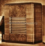
Lafayette Chassis Model B-100
|
|||||||||||||
Lafayette Radio & TV Corp. Model B-101 (left) and B-103 (right) Console Radios (radiomuseum.org image) The Radio Service Data Sheets that were published in Radio-Craft usually seem to have more information included than those published in other magazines, at least in the same era (1940-ish). It might have to do with how much material is provided by the manufacturer rather than a decision by the magazine editors. Either way, here are the schematics, chassis layout, and service info for the Lafayette Model B-100 through B-103. As with most radios built in the era, the woodwork and artistic design of the cabinet are exquisite. There are still people searching for such data, but fortunately the Internet is making it much easier to locate. None of the three models show up on eBay as of this writing. Lafayette Chassis Model B-100 (Table Model B-103; Console Models B-101, B-102) Radio Service Data Sheet
The Model B-100 Chassis is used in a series including phonograph combinations equipped with an automatic record changer. Models not equipped with record player are provided with facilities for the playing of records through the radio set (see illustration showing parts placement atop chassis and at rear). Volume and tone control are used in the same manner for phonograph reproduction as for radio reception. Selectivity at 1,000 times signal strength. 30 kc, broad. The Tone Control affords radio reception when turned to far right until a click is heard, and then backed-up for tone control; phonograph operation is obtained when this knob is turned to the far left until the click is heard, and then turned forward for tone control. Setting Buttons. - When setting-up the manual pushbutton tuning buttons, it is preferable to follow in a kilocycle sequence, starting with the lowest kc. setting at left. To set a button, unlock the pushbutton mechanism from the back of the radio receiver. On the drive pulley shaft and at the left side (from the back of the radio set) of the pushbutton tuning assembly is a locking screw (see Fig. 1). Turn the manual tuning knob until the locking screw is available and loosen it with a small-handled screwdriver. To set stations accurately do not jar the radio set or the buttons while the mechanism is unlocked. Having tuned in a station to accurate resonance, by means of the tuning eye, hold the manual tuning knob with one hand and with the other push one of the station buttons all the way in. Double-check the resonance, meanwhile holding the button all the way in, then slowly release the button. Do not touch this button again while the mechanism is unlocked. Now tune-in the second station following the same procedure; and so-on for the remaining buttons. After all the stations are set, the mechanism is locked by turning the manual tuning knob until the locking screw can be easily reached; with a small-handled screwdriver, the locking screw is then tightened.
For best shortwave reception an outside antenna and ground are recommended. A wire with an antenna marker will be found coming out of the chassis. If the loop and counterpoise foil aerials are used do not connect this wire to anything. If an outside antenna is used, connect this wire to the lead from the outside antenna. The wire which is connected to the counterpoise foil aerial should never be disconnected. On the back of the chassis is the socket for record-player connections. The cable connector must be a single shielded pin. Part No. BA224. On the top of the chassis is an A.C. phono motor socket. On the back of the chassis is a socket to which a microphone preamplifier may be connected. The speaker socket provides connections for the record cutter and power for the preamplifier. Dial lamps are bulb No, 51. bayonet pin type. |
|||||||||||||
 |
|||||||||||||
|
|||||||||||||


|
||||||||||||||||||||||||||||||||||||


