|
|||||||||||||
 |
|||||||||||||
Homodyne Reception
|
|||||||||||||
Homodyne reception, although we don't often refer to it today using that term, involves mixing the modulated signal with a local oscillator that is tuned to the same frequency so that the demodulated signal is at baseband. In other words, the result of a homodyne nonlinear mixing process is a sum frequency of 2x the signal input and the difference frequency is DC (at the low end of the modulation). That is a simplistic explanation, and this 1942 Radio-Craft magazine article goes into a little more detail about methods, advantages, and disadvantages. Why not just make things simple and make every receiver a homodyne circuit? The answer is that with homodyne operation every theoretically possible mixer spurious product will fall inband without any means of filtering them out. Sometimes it doesn't matter, but especially in today's crowded radio spectrum it just is not workable because the interference level would be too intolerable. Homodyne Reception
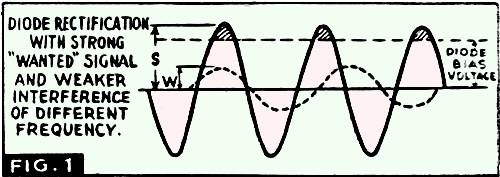
Interference and effect of bias in diode detection. The diode conducts during the parts of the cycle are shown shaded. Possibilities of the System as an Aid to Selectivity The "homodyne" system of reception is a little-known member of the family of radio "dynes," so let us first see how it is related to its cousins heterodyne, super (sonic) - heterodyne and autodyne. The word "dyne" is derived from the Greek for power, so that heterodyne merely means putting in energy at a different frequency, and becomes "supersonic-heterodyne" if the frequency difference is greater than audible (e.g. 465 kc/s), while autodyne means putting in its own power, i.e. a self-oscillating detector. Similarly, homodyne means that energy is put in at the same frequency, i.e. in synchronism with the carrier of the signal which it is desired to receive, and this is the system which may be able to help us with the selectivity problem. Interference
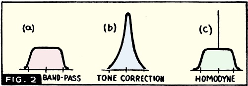
Homodyne reception compared with other methods of obtaining selectivity. Note the similarity of homodyne reception to the bandpass curve. Interference can be divided into two categories, the type which involves the carrier of the wanted signal, and the type which does not. In the first category we have the direct heterodyne between the wanted carrier and a neighboring carrier, "side-band splash" which consists of heterodynes between the wanted carrier and the side-bands of the interfering signal, and cross-modulation; in all of these the output of interference is merely proportional to the weaker of the two frequencies which are beating together so that increasing the strength of the wanted carrier makes no difference to the interference. Before, we can benefit from the homodyne principle, therefore, adjacent carriers must be spaced far enough apart for the heterodyne note to be outside the audio-frequency band, or alternatively the heterodyne must be eliminated by means of a "whistle filter" of some sort. The latter alternative is not the ideal solution, since it involves eliminating the same frequency (or rather a band of frequencies) from the program; but if the filter has a narrow enough attenuation band, it may be a tolerable method. It seems likely to take a very tong time to produce sufficient public demand for high-fidelity broadcasting on the medium-wave band to secure the sacrifice of a number of stations to adequate spacing of channels; in fact, it is a debatable point whether the introduction of wide-band U-H-F broadcasting would render superfluous high fidelity on the medium-wave transmissions, or whether the experience of really good quality would lead to a demand for it on all transmissions. Assuming, however, that we have by some means eliminated the adjacent-channel heterodyne, and taken the necessary precautions against cross-modulation (which means practically building a receiver with RF stages that never overload), the residual interference will consist of the whole modulated signal (carrier plus side-bands) of a transmitter on a neighboring frequency. Selectivity Limitations There is an essential distinction between the wanted and unwanted signals, by reason of the fact that they have different carrier frequencies, and so it may be possible to eliminate the interference which consists solely of the independent signal more effectively than heterodynes, etc., which involve the carrier of the desired signal. But first one must answer the natural question, why selective circuits? Now, reasonable program enjoyment requires a signal/interference ratio of 40 db., and for high-fidelity reception the ratio should be 60 db., i.e. a voltage ratio of 1000: I; add to this the condition that ideally one should be able to receive the weaker of two adjacent stations, say with a field-strength ratio of 10: I, and if the reader then thinks it is easy to design a receiver with adjacent-channel selectivity of 10,000: I, he need not worry about homodyne receivers. Linear Detectors The phenomena underlying homodyne reception actually occur to some extent in every receiver using a linear rectifier; (that is to say almost every modern receiver that has a reasonably strong signal tuned-in); one of the phenomena is that a linear rectifier is most sensitive to signals that are in the same phase as the strongest signal out of several applied to it. In the ordinary-diode rectifier, the diode is automatically biased by the signal so that it is only conducting for a small part of the cycle, say the extreme positive values of the voltage wave, as shown in Fig. 1. If now the amplitude of the signal is varied by modulation, there will be a change in the height of the voltage-peaks, therefore an increase or decrease of diode conduction, and this in turn will change the bias voltage so that conduction occupies the same proportion of the whole cycle as it did for the original amplitude. But the bias voltage on the diode is in fact the rectified output, so that variation of this voltage with the input represents an output signal proportional to the amplitude modulation of the input signal. Detector Discrimination Now suppose there is added to the input a smaller signal, at a different frequency, as suggested by the dotted curve in Fig. 1. The first positive peak of this second signal falls fairly well on the conduction period (determined mainly by the strong signal) and therefore increases the rectified current; but, the second positive peak falls in a non-conducting period and therefore cannot affect the output, while the second conduction period is accompanied by a negative peak of the smaller signal, which reduces the rectified output and so tends to oppose the effect produced in the first conduction period. It is obvious that the weaker signal has relatively little effect if of different frequency from the stronger one, since it is the latter which decides when the diode is conducting: as often as not the weaker signal comes up positive when the diode is thoroughly cut off by the. stronger signal, and on those occasions when the diode is conducting, the weaker signal is as likely to be negative as positive. This is only a very rough picture of the action, because the frequency-difference is greatly exaggerated in Fig. 1, and no allowance is made for changes in duration of the conduction periods when the weak signal reaches a maximum or minimum near the edge of a conduction period; when it has been properly worked out mathematically, the ratio of the AF outputs due to modulation on the strong signal S and on the weak signal W is approximately 2S2/W2, and the phenomenon is known as "the apparent demodulation of a weak signal by a strong one" (or, more briefly, "rectifier discrimination"). To see how useful this is, suppose that by means of selective circuits we have made the wanted station supply a carrier voltage 10 times greater than that of the unwanted station at the input to the detector: this represents a signal/interference ratio of 20 db., which would not be very good. But if S/W = 10, the ratio of the audio-frequency output voltages is 2S2/W2 = 200, or 46 db., which is tolerably satisfactory. Selectivity and Tone Correction In early receivers this gain from linear detection was not always obtained, because the signal level at the detector was so small that the detector did not function as an on/off device, as described in connection with, Fig. 1, but as an approximately square-law device which conducted rather better in one direction than the other; since the stronger signal was thus not sufficient to stop conduction for part of the cycle, the weaker signal could always produce some effect, regardless of its phase relation to the stronger signal, and no rectifier discrimination was obtained. One of the first specialized systems to obtain this advantage (though the mechanism was not at first understood) was the "tone-correction" type of receiver. The RF circuits (including the RF, if any) were made. of maximum Q, so that a very high gain was obtained at carrier frequency and low modulation frequencies, though the higher sidebands were relatively cut by a very large amount, and after detection the severe top cut was corrected by AF tone-correction circuits. Rectifier Discrimination Owing to the strong carrier, this gave good "rectifier discrimination," but the top boost in the AF circuits exaggerated any harmonics produced in the process of rectification or by asymmetry of the RF circuits: 2 per cent to 5 per cent of harmonics in the output of the detector could become something like 50 per cent harmonics in the loudspeaker, and the popularity of this system was short-lived. In fact, it died a natural death with the development of the super-heterodyne and AVC; the latter required a large enough amplitude at the detector to insure linear rectification, while the former provided the means of getting sufficient gain, and at the same time made it technically feasible to use selective band-pass circuits with a square-topped response, giving good adjacent-channel selectivity without requiring tone-correction. But good tuned circuits are expensive and critical in adjustment, even when they work at a fixed intermediate frequency, and of recent years the number of high-powered transmitters has been greatly increased, so that once again selectivity, is a problem. The tone-correction system was on the right track, but the top boost in the AF circuits was an intolerable nuisance; the solution then appears to be to increase the amplification of the carrier only, while retaining a uniform amplification for all the sidebands from lowest to highest, and this is the homodyne system. The three systems are represented diagrammatically in Fig. 2: diagram (a), normal receiver with square-topped response curve; (b), sharp circuits requiring subsequent tone-correction; and (c), homodyne receiver with carrier only accentuated. If wanted and unwanted signal reach the detector with equal amplitudes, the result will be a hopeless jam; but if we can add to the desired signal an artificial carrier of just over 30 times the existing carrier strength of either, we immediately obtain a rectifier discrimination 2S2/W2 equivalent to 66db., and reception is perfect, without any disturbance of the audio-frequency response characteristic. In fact, the audio-frequency performance is improved, because an incidental advantage of the homodyne system is the elimination of one source of distortion in the detector. With a normal diode detector feeding a load circuit whose AC impedance is less than its DC resistance, distortion occurs when the depth of modulation exceeds some value such as 75 per cent (depending upon the ratio of AC to DC load); but when the carrier has been artificially increased for homodyne reception, the depth of modulation will always be small, so that the ratio of AC to DC detector loads is no longer critical. Artificial Carrier The problem, of course, is how to produce this artificial carrier, which must be exactly in phase with the original carrier of the wanted signal, and there are two main lines of attack. According to one method, the carrier is selected from the input by some form of filter, and amplified more than the sidebands. There are various methods of inserting the filter in the circuit, and a method of selective negative feedback has been suggested as suitable (Patent No. 533784, abstract published in Wireless World, Jan., 1942); but this does not go far towards solving the problem, for the filter still has to have a very narrow response, even if it is connected in the negative-feedback line instead of in a straight-forward coupling between two stages of amplification. It can be assumed that the receiver is a superhet., and probably the IF will be 465 k.c. while the lowest audio-frequency can be put at 50 cycles per second. (Any rise in the response to frequencies below 50 cycles per second can be easily offset by a falling-off in the characteristics of loudspeaker and AF amplifier.) The carrier-selecting filter must therefore have a band-width of not more than 50 cycles per second in 465 k.c./s which is a fairly difficult proposition even for a crystal filter. In addition, the intermediate frequency must then be correct to something like 20 cycles per second, which means that both the accuracy of tuning and the stability of the local oscillator must be as good as 20 parts in a million for the higher-frequency end of the medium-wave band, and proportionately better for short-wave working. The other line of attack is to use a local oscillator, somewhat similar to the IF beat oscillator used for CW reception, to generate the extra carrier voltage, and synchronize this oscillator with the signal carrier. Probably most experimenters have done this at some time or another with a receiver using a reacting detector: if the reaction control is smooth enough, reception free from beat note can be obtained although the set is gently oscillating. But this is not really a fair example of homodyne reception, since it involves also a great increase of Q of the tuned circuit, and hence loss of high audio frequencies, which would not be present with a separate oscillator. In any case, this is hardly a method of reception to let loose on the general public. But granted the use of a superhet circuit and a separate oscillator tube for generating the carrier, which is then a practically constant frequency, there are possibilities in the way of designing the oscillator specially so as to hold synchronism over as wide a range of frequency as possible, though even so, tuning would need to be exceptionally accurate, and oscillator drift small. One of the troubles is that on 100 per cent modulation the carrier of the signal to be received falls to zero, and the homodyne oscillator would then be almost certain to drop out of synchronism. (Some data on the effect of modulation on the synchronization of an oscillator were published by Eccles and Byard in an article in Wireless Engineer, Jan., 1941, Vol. 18, p. 2.) Another snag is that the artificial carrier from the local oscillator would predominate in the output from the detector, so the DC component could not be used for AVC, which would have to be derived from an independent IF circuit free from carrier injection. Possibilities of Development It is clear that a good deal of development would have to be done before a commercial broadcast receiver could be built on the homodyne principle. (Perhaps the problem might appeal to some of the amateurs whose transmitters are close down "for the duration.") But the whole history of radio is the development of tricky laboratory apparatus into something approaching a foolproof piece of household equipment. For example, think back to the days of the earliest receivers and compare them with the present-day superheterodyne. Instead of single-knob tuning and a dial engraved in k.c., meters, and station names, one used to have two dials, marked only in degrees, which had to be simultaneously at the correct setting before any but the local station could be received. Instead of AVC to keep a constant output level, there used to be a reaction control which usually needed progressive adjustment as one tuned round the waveband, in order to keep a high level of sensitivity. Instead of independent volume and tone controls, there would probably be a reaction control supplemented by a rheostat in the filament of tile RF tube to control gain, and the expert would balance reaction and gain adjustments to secure the desired volume and band-width. Looking at this transformation of the radio receiver, and the parallel transformation of the television receiver from a 3D-hole scanning disc in front of a neon lamp into the cathode-ray type of receiver, it does not seem unduly optimistic to say that the difficulties inherent in the homodyne system of reception could be overcome in a commercial design. -Wireless World (London).
Posted December 14, 2023 |
|||||||||||||
 |
|||||||||||||
|
|||||||||||||


|
||||||||||||||||||||||||||||||||||||


