|
|||||||||||||
 |
|||||||||||||
End-Fed Zepp Antenna for Receiving
|
|||||||||||||
Any mention of a "Zeppelin" conjures up thoughts of disaster in the form of the famous Hindenburg incident at Lakehurst, New Jersey, back in 1937. Fortunately, not all things "Zepp" are bad news. The end-fed Zepp (short for Zeppelin) antenna is as popular today as it was when the Germans developed it for use in the Zeppelin airships. One of the major advantages to an end-fed Zepp is that it is, as the name suggests, fed from the end rather than in the center like a dipole. The configuration makes installation simpler than a dipole. Being so simple in construction, the Zepp handily functions as a multi-band harmonic antenna so it is useful on, for instance, the 160, 80, 40, 20, and 10 meter Ham bands. Many companies (e.g., MFJ Enterprises) sell Zepp antennas as well as the modified Zepp known as a J-pole antenna. This article will help you make your own Zepp antenna system, including a matching network. End-Fed Zepp for Receiving R. H. Newkirk, W9BRD
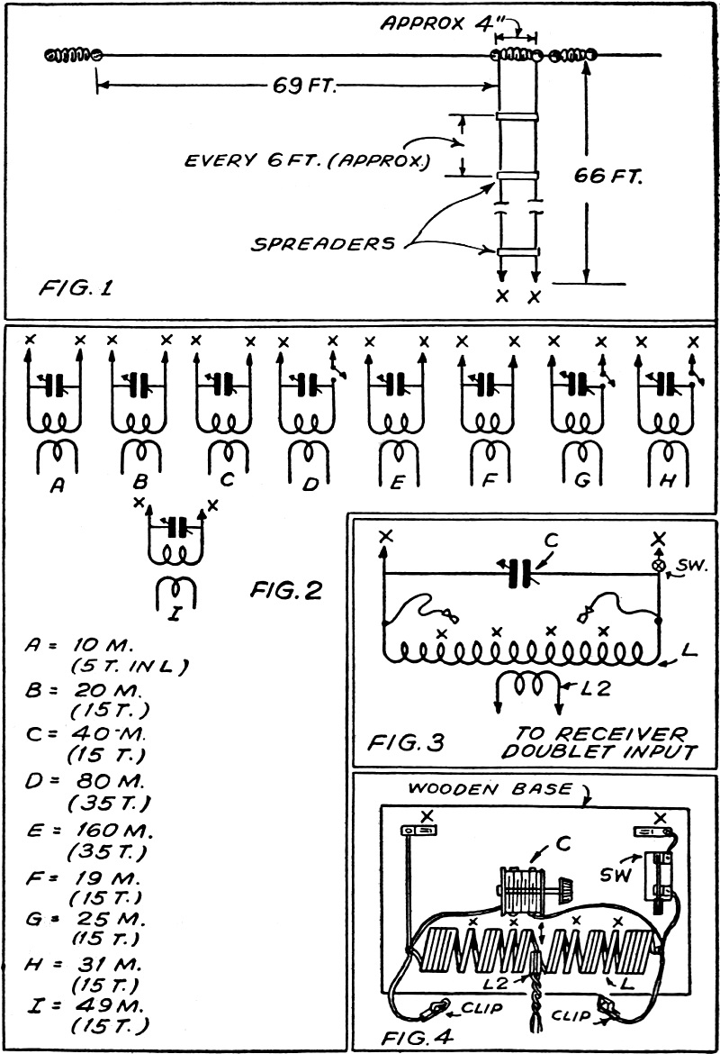
The illustration at the above shows the simple method of erecting and connecting the end-fed Zepp aerial for receiving purposes. How to tune it is explained in the accompanying article. Many valuable pointers are given by the author in this interesting article, describing the use of a simple antenna which will markedly improve your reception. Details of the proper tuning unit to use are also given. In an earlier article I sought to point out the advantages possessed by Zeppelin-type antennas for reception as compared to doublets or random-length wires. This dealt with an antenna combination for top performance in the larger short-wave broadcast bands and the ten and twenty meter amateur radiophone bands. As pointed out, the chief advantages of the Zepp, especially the type fed in the center (also called "tuned doublet"), is its ability to resonate efficiently over a considerably wider band of frequencies than the doublet, and to operate on harmonics of the fundamental frequency (the frequency for which it is cut). Center-feed was chosen for the purpose of resonating in the short wave broadcast bands because, as these bands do not occur in harmonic relation, its property of a more balanced resonance than the end-fed Zepp at frequencies slightly lower or higher than the frequency for which it is cut, or its harmonic frequencies, made it to be preferred. A Zepp antenna for coverage of the amateur bands is a different proposition. The bands lie in quite good harmonic relation, and so one end-fed Zepp approximately 69 feet long (flat-top only) will operate efficiently on the 40, 20 and 10 meter ham bands. By use of feeders about 66 feet in length it is also possible to use the antenna as a Hertz on 80 and a Marconi on 160, resonating it in each band for best signal-to-noise ratio. (The 160 meter case is subject to exception as will be pointed out.) Also, those interested in BCB DX can, with a little experimentation, get the antenna to resonate in the broadcast band as a Marconi with a consequent improvement in reception. Now, a few words on present amateur band DX listening may not be out of order. Recently ham DX has been much curtailed; in fact, English-speaking foreign stations in the ham bands are rare indeed. One still has our Pacific islands and other possessions to hunt for, but these are none too plentiful either. S.W.L.'s Learn Spanish! South American 'phone hams are still pounding through on the 20 and 40 meter bands, however, and the short wave listeners who have acquainted themselves with the Castilian alphabet and numerals are still adding to their DX logs. I know of many who never knew a word of Spanish before and who are growing quite proficient at the language, through their DX listening. Along this point also, it might be pointed out that our government has urged Americans in general to become more familiar with the Spanish tongue, in line with promoting closer Latin-American relations. Of course, to learn a language fluently requires an able instructor. But a short wave receiver and a textbook can do a pretty fair job. Anyway, not to digress further, there are still many DX stations in the ham bands to be logged by those who specialize in this branch of listening. Then, too, there is the embryo ham, who is just getting acquainted with the amateur frequencies and is learning his code by daily amateur band sessions. The antenna described here will be recognized by hams, as an ordinary Zepp. This type of "skywire" is perhaps the most widely used antenna on the 20 and 40 meter bands for amateur transmitting-and it makes just as good a receiving system as transmitting. It is used here at W9BRD for both purpose and, as is shown in Fig. 2F, G, H and I, it can also be used to advantage in the short wave broadcast bands for reception,. As has been said before, a Zepp meant only for receiving can be much less elaborate than one for transmitting. The insulation problem is minimized and wire size is unimportant. The feed-line should be close to 66 feet in length, if tuning is to conform with that given in this article. Other lengths will require considerable cut-and-try experimentation in the tuning unit, in order to obtain resonance. Bending the feed-line when necessary should not cause complications if not carried to excess. Wooden spreaders or others of insulation material should space the feeders approximately four inches apart, from the end or the flat-top to the tuning unit. Other pointers on construction of Zepp feeders can be found in the article on the "Center-fed Zepp for Receiving." (See June issue of this magazine.) Tuning Unit Now for the tuning unit. It is diagrammed in Fig. 3 and pictured in Fig, 4. The coil, L, is wound of No. 12 enameled . wire, self-supporting. Its diameter is approximately 2 inches. The clips extending from each end of the coil are used to "short out" the necessary turns when a smaller coil is desired. Three values of L are used; 35, 15 and 5 turns. Hence, L consists of 35 turns, close-wound, with provision made for shorting out portions of the coil. The enamel should be scraped clean from a section of the wire 10 turns from each end, and also 15 turns from each end. At these points the winding should be spaced a bit to enable the clips to grip. In the center of the coil should be a space just wide enough to admit the link coil, L2. The link coil could be wound around L but the spacing permits variation of coupling between the unit and the receiver by simply pulling L2 in and out. The link coil connects to the doublet input of the receiver, and consists of three turns of insulated wire of any size, about 1 3/4 inches in diameter. The smaller the wire the better, since less spacing will be necessary in the center of L. The condenser, C, may be any variable receiving type condenser with a capacity of at least 200 mmf. If you use one with side trimmers, open these as far as possible, so that a low minimum capacity can be obtained. The single-pole single-throw switch, SW, is used to detach the reflecting, or "dummy" feeder, when it is desired to resonate the antenna for reception in the 80, 25 and 31 meter bands. The feeders connect to the tuning unit at the points marked X. Normally, on 160 meters, one would tune 135 feet or so of wire against ground as a Marconi. But this antenna can be tuned to this band in the same manner as a Zepp, using a coil of approximately 35 turns. This provides good reception in the 1.7 mc. band but the antenna is not operating as an orthodox Zepp. Whether or not it operates as well as a Marconi would is not certain, but it is much simpler to adjust in this case. Those interested in 160 meter reception can determine this for themselves. Tuning and adjusting a Zepp for reception was discussed in the article previously mentioned. The procedure is simple and for those who missed it I will go through it again. We will take, for instance, the twenty meter band. With the receiver tuned to an amateur phone signal (be sure it isn't a broadcast image) and the tuning unit condenser at a random setting, insert the link, L2, into the center of L as shown in Fig. 4. The receiver signal should be very weak. Now rotate C until there is a noticeable increase in signal strength. The point at which the signal is loudest is the point of resonance for the Zepp. Now decrease the coupling by pulling the link gradually out of L until optimum coupling is reached. This is the minimum amount of coupling possible with maximum signal strength. Too much or tight coupling at this point will cause the resonance point on the condenser to become broad and will decrease the signal-to-noise ratio. Too little coupling will cause the signal strength of received signals to drop. This variation of coupling gives you an effective R.F. gain control if your receiver is not already equipped with such. Once the knack of making this adjustment is learned you will be able to switch the antenna from one band to another in a jiffy. This antenna makes a very good transmitting wire for work on all bands from 160 to 10 meters in restricted locations, where longer wires are not possible. Efficiency is highest on 40, 20 and 10 meters where it operates as a Zepp, but all states have been worked on 80 meters, using less than 100 watts. On 160 meters both coasts have been contacted on CW with 15 watts input, the 135 feet of wire tuned against a radiator ground as a Marconi.
Posted October 28, 2022 |
|||||||||||||
 |
|||||||||||||
|
|||||||||||||

|
||||||||||||||||||||||||||||||||||||


