|
|||||||||||||
 |
|||||||||||||
An Automatic Program Sensor
|
|||||||||||||
The effort to block advertising on radio broadcasts has been going on for about as long as advertising has been in use, as evidenced by this 1934 article in Radio-Craft magazine where a "robot" advertising silencer device is presented for removing "superfluous advertising." Headlines from a few weeks ago announced Apple's program for blocking ads that appear on websites, causing a big to-do about how all the "free" content would be jeopardized since it is the advertisers who pay for the music and other programming to be delivered to the user. We also have the blocking of conservative opinion and fact reporting on social media platforms. Without the convenience and economy of software to do the job in 1934, however, fairly complex discriminator circuits were used to detect and mute the "garrulous announcer or advertiser" between regular programming. It's pretty funny to read about how annoyed people were with the advertisements - just like today. I hate the online ads that automatically play audio rather than providing an option to listen. Besides, those video and audio ads consume a lot of bandwidth when downloading, so that delays the website content from loading as quickly as it could otherwise. Most of my radio listening is via the Internet, and of course those broadcasts are chock full of advertisements. There is an option to pay a monthly subscription to avoid the ads, but they don't offend me quite that much ;-) An Automatic Program Sensor
No longer will it be necessary to endure half an evening hearing detailed advertisements on tombstones, dog biscuits, soap or "laughing water" in order to spend the remaining half enjoying entertainment. Geo. P. Adair, an electrical engineer, has just invented a novel device that seems almost human in its discriminatory powers to regulate an incoming radio program. It automatically cuts off the garrulous announcer or advertiser who sandwiches an "ad" between every note of music or tactlessly carries his advertising speeches to the point of nausea. This special receiver makes it possible for the radio audience to take as much or as little of advertising as they please, or to have an uninterrupted musical program if they so desire. Of course, like many other inventions this one may never be put to wide practical use. In the first place, the people of the United States are well aware that the advertiser is the one who pays for the notwithstanding immeasurable pleasure afforded them by radio. Far more fortunate are Americans than the people of European countries where tax is levied on individual radio equipment. In Germany, for example, the postman collects a radio tax at regular intervals that is set by the government.
Fig. 1 - Circuit diagram illustrating arrangement of a radio receiving set embodying a means of discriminating between music and blatant advertising. See text for complete explanation.
Fig. 2 - Automatic switching arrangement from receiver to phonograph when lengthy talks begin.
Fig. 3 - A method of censoring advertising by automatically switching on another program.
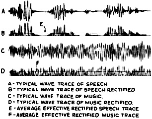
Fig. 4 - The differences between speech and music in wave form are clearly shown by the curves above. It will be noted that there are open spots in the speech curves, which permit the censor to function. And so that automatic "censor," just patented by its inventor George P. Adair, is explained to us not as a means to annihilate advertising, but rather as a restraint to be used when necessary. Or, as John B. Brady, attorney for Mr. Adair, aptly put it, to eliminate advertising would be to kill the goose that lays the golden egg for broadcasters. It is quite satisfying to our romantic conception of the development of an invention to know that the material used principally in the construction consisted of a baby bed, a wastepaper basket, coffee and baking powder cans, pie and cake pans and other discarded articles assembled by the inventor. Mr. Adair has built a number of these radio sets which operate splendidly. Broadly speaking the invention relates to radio reception and particularly to a special circuit arrangement for radio broadcast receivers. Mr. Adair arrived at his conclusions and subsequent invention by basing it on the fact that the characteristics of the speaking voice are different from those of vocal and instrumental music. Except in very unusual cases there are few definite pauses in the latter, while in the speaking voice there are numerous and quite definite pauses between syllables and words, and quite long pauses between phrases and sentences. If the electric waves caused by speech are rectified, the current resulting is of a pulsating nature, while in the case of music it is a direct current that varies little in amplitude. The receiving apparatus serves in various ways. A circuit arrangement may be fixed so that silence replaces the extended advertising talk, and nothing is heard until the music is again begun. By operating another switch, the device automatically works so that it simply changes over to another station when music is discontinued on one, thereby obtaining a constant musical program. Or again an arrangement may be employed whereby the sound-reproducing system is switched to an automatic phonograph or other form of automatic recording device, which will permit the reproduction of a desired record between the musical broadcasts. As soon as musical or vocal selections are again being broadcast the receiver automatically responds again to the radio broadcast. If it is desired to render the speech-eliminating system inoperative, or in other words to have the set perform as a normal radio broadcast receiver, one simply closes a designated switch. The system of this special receiving arrangement, in detail, is as follows: You may note by Fig. 1, that there is a receiving circuit connected to an input-circuit including primary winding 3 of the coupling transformer 4. Secondary winding 5 of coupling transformer 4 is tuned by variable condenser 6. In turn, the tuned circuit connects to the input system of an R.F. amplifier including electron tubes 7, 8 and 9. At this point the detector tube 10 connects to the output circuit of the R.F. amplifier system. The tuning elements 6, 11, 12 and 13 for the R.F. stages and the detector stage of the receiving arrangement are at the same time controlled as shown through dotted line 14. The output circuit of the detector tube 10 connects to the A.F. amplifier system made up by electron tubes 15 and 16 connected in parallel for obtaining greater power output. The output circuit of the A.F. amplifier stages 15-16 includes transformer 17, the primary of which is shown at 18 connected to the output circuit of tubes 15 and 16 through the coupling condenser 57; and the secondary winding of which is indicated at 19 joined to the sound reproducer marked at 20. Coil 21 of the electro-dynamic speaker system composing the loudspeaker 20 is movable and is connected in series with contact 22 of a relay at 23. The field winding of the reproducer 20 is shown at 24 suitably energized from the output circuit of the detector tube 10 as shown at 26. This path leads to auxiliary control tube 27. A selective filter coupling device provides the input circuit of tube 27. A resistor 31 completes the input circuit to the auxiliary tube 27. Grid 27c, of control tube 27, is normally biased to a negative potential of such value that the tube works on or below the lower knee of the characteristic grid-voltage, plate-current curve. Resistor 31 provides this negative potential, and is connected to the ground which is maintained at a negative potential in relation to cathode 27a through the voltage drop caused by a current flow through resistor 48. The circuit of the latter is completed through resistor 50 and conductor 34 to the power supply. Condenser 51 serves as a smoothing unit. Output of control tube 27 leads from the anode 27b to the electro-magnetic helix 32 forming part of a relay. The circuit of 32 is completed with a resistance 33 which goes through at 34 to the power supply circuit. The relay 32 controls the armature tongue 37 which moves with relation to contacts 38 and 39. A vacuum tube relay at 41 has an input circuit passing through the conductor at 42, which connects to tongue 37 of the relay. When the armature moves against contact 39, increased negative potential is placed on the grid 41c of tube 41. This is caused by a negative charge which collects on the grid condenser indicated at 47 through resistance 40 and connection to ground which is normally kept at negative potential with respect to cathode 41a through resistance 48. When the negative charges are placed on the grid, it results in decreasing the plate current in the output circuit. The latter is completed through resistance 33 to the path of positive plate potential through conductor 34. If the armature tongue 37 is held contacting 39 a given period depending on the resistance and capacitance and the operating constants of the tube used, the negative biasing potential increases until the plate current is decreased to a low value which in turn de-energizes the relay. The relay contacts are thus closed, finishing the circuit through the voice-coil 20 of the dynamic loudspeaker. The device is now ready to receive vocal or instrumental music. When the armature tongue is contacting, the charge will be reduced by leakage through resistance 45 until the potential on the grid will allow enough current to flow in the output circuit to energize relay 23 and to open the circuit to the voice-coil of the loudspeaker making it inactive. Substitute Programs When the phonograph is to fill in musical lapses, a system is used, Fig. 2, that switches the A.F. amplifier portion of the broadcast receiver to the control portion of a recorder circuit by which recorded programs are reproduced electrically. To do this an auxiliary unit is coupled to the output circuit of the R.F. amplifier stage and connected to a relay control system. The latter connects the phonograph actuating circuit into the input of the detector tube for using the detector tube as part of the A.F. amplifier system, This includes the R.F. detector stage which is coupled through a conductor and coupling condenser to the output of the R.F. amplifier. The other side of the input circuit to the detector stage is finished by the impedance circuit to the ground. The output of the detector stage is coupled through the coupling circuit with the input circuit of the A.F. corrective tube. A filter circuit is used between the output circuit of the R.F. detector and the input circuit of the subsidiary detector tube. In other words, filter elements at three points are arranged in the circuit with the A.F. rectifier tube to differentiate the range of voice frequencies and the range at musical frequencies to which the detector responds. When the relay is energized due to lengthy speaking or cessation of music, contacts close which in turn cut off the circuit to the driving motor and start the twitch of the automatic phonograph. In cases when it is desired only to eliminate extended speech and not to substitute any other program, this is accomplished by opening the circuit to the loudspeaker. This and the other previously mentioned ways in which the receiver serves is done merely by opening of the various switches. A- multi-point switch operated by a single control may be used for these various switching operations. A system for substituting other radio programs for those in which undesirable speech predominates is shown in Fig. 3. The speech and music wave-form difference upon which all these systems depend for their operation is immediately apparent to those who can diagnose the graph shown in Fig. 4. |
|||||||||||||
 |
|||||||||||||
|
|||||||||||||


|
||||||||||||||||||||||||||||||||||||


