|
|||||||||||||
 |
|||||||||||||
Why Key Clicks? |
|||||||||||||
Waveform shaping is essential in today's crowded communications spectrum. Spectral masks are precisely defined in order to prevent "spreading" beyond the allocated frequency ranges at defined power levels. Whenever anything other than a continuous sinewave is being broadcast, there is spectral content generated in addition to the fundamental frequency. A Fourier transform of the waveform reveals which frequencies at what power levels comprise the waveform. The CW (continuous wave) signal used by Morse code operators is a pure sinewave (or nearly so), but there is a spectral problem with it every time the signal turns on or off because of the square-ish edges involved during switching. RC networks are used in the transmitter circuits to tame the edges so that they do not turn on and off so quickly and in doing so reduce the extraneous frequency content. Author George Grammer argues that even though the signal could theoretically be made "clickless" (aka "chirpless"), there is an auditory benefit to the clicks or chirps that aids operators listening to high speed code transmissions. See also: "What Causes Clicks?" by W8JI (thanks to Kevin A. for the link) Why Key Clicks? ... The Necessary Bandwidth for C. W. Signals
By George Grammer,* W1DF Are key clicks necessary? There are those who contend that they are, the argument being that at high code speeds "soft" dots and dashes become unreadable. The issue is clouded by personal preferences as to how a keyed signal should sound, just as there are personal preferences about voice "quality". Putting aside such subjective factors, the question" Are key clicks necessary?" can be rephrased: "How much bandwidth is necessary for good code transmission?" There is a long-standing answer to this last question. It is to be found in the international regulations, where the necessary bandwidth is specified as the keying speed in bauds multiplied by a factor which is 3 for circuits where the signals are steady, and 5 for circuits where fading is bad. To see how this specification affects amateur practice it is necessary first to review a few fundamental keying definitions.
Fig. 1 - Upper: A code element is the length of the shortest pulse-a dot or space in International Morse Code. Lower: A succession of alternating dots and spaces considered as an a.c. square wave superimposed on the average value of current or voltage. The fundamental sine-wave frequency for such a square wove also is shown.
Fig. 2 - A d.c. circuit which would generate the square waves shown in Fig. 1.
Fig. 3 - A shaped dot and its relationship to closing and opening the key. Keying Speed The building block of telegraph transmission is the code element, the time duration of the shortest keying pulse. In International Morse code the shortest pulse is one dot. Since, by definition, the space length is equal to one dot length, a space is also a code element. This is shown in Fig. 1, where the top drawing could represent a d.c. circuit being keyed in a string of on-off dots and spaces. Such a circuit is shown in Fig. 2. If the string of dots is continuous and fast enough to let the meter's pointer settle down at an average value of current, the meter will read just half what it would with the key closed. This is because the current is off just the same length of time as it is on. We can look at this continuously keyed circuit, therefore, as one in which the keyed signal is alternating about an average direct current equal to the meter reading. Thus we have an a.c. square wave superimposed on the average d.c. One cycle of this square keying wave runs from the beginning of a dot through the following space to the beginning of the next dot. This is shown in the lower drawing in Fig. 1. Obviously, one cycle of the keying wave is equal to two code elements. Any repetitive waveform, of whatever shape, can be reproduced by a collection of sine waves in harmonic relationship to a lowest frequency which is the same as the basic repetition rate of the waveform under consideration. This" fundamental" sine wave is also sketched in Fig. 1. If we are sending 25 dots per second, for example, the fundamental keying frequency is 25 cycles per second. By adding the proper harmonics to the fundamental, the actual square-wave shape can be approached as closely as we like. Getting those square corners, though, takes very high-order harmonics - harmonics whose frequencies may be many times the fundamental frequency. This means that the circuit bandwidth has to be large compared with the fundamental keying frequency if square-wave keying is to be closely approximated. Fortunately, it isn't necessary to use anything like a real square wave for good keying. It has long been recognized that a keying waveshape which contains only the third harmonic of the fundamental is quite sufficient for good copy. This is the reason for the factor 3 in the regulations. On this basis, a 25-cycle fundamental would take only a 75-cycle bandwidth. It is also recognized that when the signal-to-noise ratio is poor a somewhat sharper keying wave is needed; this explains the factor 5, meaning that the fifth harmonic of the fundamental keying frequency is transmitted. Keying Speed
C.W. keying can be clickless - without signal deterioration at any sending
speed an amateur will use.
Transmission speed is ordinarily expressed in bands rather than in cycles per second. A baud is one keying element per second; therefore one cycle per second is equal to two bauds. In International Morse a dash is three code elements long, but since a dot or dash has to be followed by at least one space, a dot is considered to consist of two code elements and a dash to have a total of four. Thus One dot = 2 code elements One dash = 4 code elements Additional space between letters = 1 code element Additional space between words = 2 code elements The letter C, for example, consists of Dash - 4 code elements Dot - 2 code elements Dash - 4 code elements Dot - 2 code elements Space - 1 code element, making a total of 13 code elements. If it is sent in exactly one second, the speed is 13 bauds, and the fundamental keying frequency is therefore 6.5 cycles per second.
Fig. 4-A - Shaped dot generated at a 46-baud rate with approximately 5·millisecond rise and decay times. Vertical lines are from a 1000-cycle signal applied to the Z axis for timing.
Fig. 4-B - The corresponding frequency spectrum as shown by a Panoramic analyzer. Distance between vertical lines is 50 cycles, for a total bandwidth of 500 cycles for the entire picture. Decibel scale at the left is with reference to the key-down signal amplitude which was set at 0 db. in this and the spectrum plots of Fig. 6. The fundamental frequency components are 23 cycles on either side of the carrier frequency, which appears slightly to the left of the vertical zero axis. Note that the odd harmonics of 23 cycles are predominant, the even harmonics being relatively small. The 3rd harmonics are 20 db. down and the 5th harmonics are about 28 db. down. Higher-order harmonics are practically negligible. With 7-ms. rise and decay times the 5th harmonics are down 30 db. This method of measuring keying speed is exact, while "words per minute" is rather nebulous. The w.p.m. figure is dependent on the selection of words of average length; several such selections have been made, and the resultant w.p.m.-per-baud factor varies from a shade over 1 to about 1.2. Thus a keying speed of 25 bauds can be interpreted as something between 25 and 30 w.p.m, More to the point, a speed of 50 bauds is about as fast as any amateur will go with hand keying, so our opening question boils down to this: What bandwidth is necessary for a speed of 50 bauds - that is, 50 to 60 w.p.m.? It seems reasonable to assume that no one would attempt such a speed, unless signal were good. Under such conditions the international regulations say that the necessary bandwidth is 3 X 50, or 150 cycle s. This is small enough to be contained easily within the passband of the narrowest c.w. filters used in today's receivers. In passing, it should be noted that the fundamental frequency is 25 cycles when the speed is 50 bands, so transmitting the third harmonic along with the fundamental calls for a keying bandwidth of only 75 cycles. The extra factor of 2, above, comes in because when the keying wave, which is modulation just as much as voice, is applied to a radio-frequency carrier two sets of sidebands are generated. Thus the radio-frequency bandwidth is twice the keying bandwidth. Shaping What we have been discussing so far is the necessary bandwidth for a very special case - an interminable string of dots and spaces of equal length. Actual code transmission consists of dots, dashes, and spaces - the latter of various lengths - and since whatever shaping is used will be applied to the beginnings and ends of dots and dashes alike, it is more appropriate to talk about the rise time at the beginning of each pulse and the decay time at the end. Ideally these two times would be equal. Practically, they are seldom so, although they can be made approximately the same by careful adjustment of the shaping circuits. Also, the shapes of the rise and fall of amplitude differ when practical shaping methods are used. There is a useful approximate formula which states that the bandwidth of a pulse is equal to 1 divided by twice its rise or decay time, whichever is smaller.1 The rise (or decay) time is defined as the time required for the pulse to go from 10 percent to 90 percent of its maximum amplitude. For a 75-cycle bandwidth this formula gives 6.7 milliseconds as the rise or decay time. Alternatively, we may consider that we have a 200-cycle i.f. passband available in the sharpest receiver, and for such a bandwidth find that the formula gives a rise or decay time of 5 milliseconds. In other words, a rise or decay time of 5 to 7 milliseconds is short enough for the fastest hand keying speeds and a signal so shaped occupies no more bandwidth than can be handled by the sharpest receiving filter. Furthermore, careful listening tests show that a keyed signal using these rise and decay times has no clicks. The transition from key open to key closed, while difficult to describe accurately in words, is a moderately firm thud which does not have any resemblance to the sharp sound that distinguishes an unmistakable click. 1 Ref Reference Data for Radio Engineers, International Telephone & Telegraph Co., New York; fourth edition, p. 542.
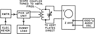
Fig. 5 - Setup for obtaining the scope patterns shown in Figs. 4A and 6A. The pickup unit and tuned scope coupler can be made as described in QST for October 1964 (also in Single Sideband for the Radio Amateur, Fourth Edition, p. 196).
Fig. 6-A - Dot with no intentional shaping; conditions otherwise the same as in Fig. 4. There is a finite decay time inherent in the keying system, but the rise time is quite short.
Fig. 6-B - Corresponding frequency spectrum over a 500-cycle bandwidth; carrier frequency slightly to the right of the vertical zero axis.
Fig. 6-C - Same as B, but with the carrier set at -0.4 to show outlying components not visible in B. Bandwidth to the right of the carrier is 450 cycles. Note that the odd-harmonic components have not dropped to -40 db. in this range.
Fig. 7 -Scope photograph of a received signal having essentially no shaping. The spike at the leading edge is typical of poor power-supply regulation, as is also the immediately-following dip and rise in amplitude. The clicks were quite pronounced. This pattern is typical of many observed signals, although not by any means a worst case. The signal was taken from the receiver's amplifier (before detection) using a hand-operated sweep circuit to reduce the sweep time to the order of one second. Weight At a speed of 50 bauds one code element occupies 20 milliseconds (1 sec. divided by 50). Fig. 3 shows, in a somewhat idealized way, the effect of shaping with 5-ms. rise and decay times. In this drawing it is assumed that the output rises to 10 percent of its maximum amplitude 1 ms. after closing the key, and decays to 90 percent 1 ms. after opening the key. The effect of shaping is to lengthen the dot duration, overall, but to shorten the time during which the amplitude is maximum. This immediately poses another question: What is the effective length of such a dot? An ultraconservative viewpoint would be that the dot length is the time during which the amplitude is within 1 decibel of maximum. This is approximately the time between the 90-percent amplitude points. The keying shape shown in the drawing would have a dot length of 15 ms. (A to B) and a space length of 25 ms. (B to C) on this basis. A more realistic assumption would be that a 3-db. drop would establish the dot and space times, in which case the dot length is 18 ms. and the space length 22 ms. In this drawing the dot and space lengths reach equality when the amplitude is down 6 db. Since reception is by ear and not by machine, the question of the effective dot length cannot be resolved with complete objectivity. There appears to be no actual problem in recognizing the dots as separate entities with shaping of this general order. If they seem light to some and heavy to others, it is easy to change the keying weight slightly so the dwell time differs somewhat from the space time. Or the receiving operator can readily apply audio clipping to a dot that seems short; 6 db. of clipping would make the dot and space times equal in this example. Clipping also shortens the rise and decay times and makes the keyed signal sound "harder" - which some like. Neither of these measures increases the keying bandwidth. The operators at both ends of the circuit have a great deal of control - control that does not increase the interference to stations trying to operate on nearby frequencies. Keying Waveshapes Most, if not all, shaping systems in amateur c.w, transmitters use the discharge of a capacitor to slow down the break end of a code character. The waveshape of the decay is superficially exponential, resembling the discharge of a capacitor through a simple resistance but is considerably modified by the circuit conditions. However, the general effect is that the transmitter output decay rapidly at first and then tails off more and more slowly. This curve is inverted on the make end of the character, rising rapidly at first and then slowly approaching the maximum amplitude. The critical points in both shapes are the starting points, where the change from off to on, or from on to off, begins. With truly exponential curves this sudden transition from "nothing " to "something" on make would result in a long string of harmonics - i.e., a wide band would be generated. Fortunately, tube characteristics tend to eliminate the sharp corners on both make and break. A typical dot waveshape with blocked-grid keying is shown in Fig. 4A, where the rise and decay times have been adjusted for approximately 5 ms. at a keying rate of 46 bauds, the highest speed of the electronic keyer used. The corresponding frequency spectrum is shown in Fig. 4B. (If anyone doubts that a keyed signal consists of a carrier and sidebands this picture should settle the question.) The vertical lines in the scope pattern, A, are the peaks of a 1000-cycle liming wave applied to the intensity or Z axis of the scope. The setup for making patterns of this type is shown in Fig. 5, and can easily be duplicated by anyone having an electronic keyer, a general-purpose oscilloscope, and a 1000-cycle oscillator having a reasonably pure waveform. The vertical lines mark 1-millisecond intervals. Timing is essential with oscilloscopes of the type ordinarily found in amateur stations, since the "linear" sweep is usually not very linear at the 20- to 25-cycle sweep rate required for showing just one dot and its accompanying space at a 40- to 50-baud rate. Fig. 6A shows a dot at the same speed as Fig. 4, but with no shaping, and Fig. 6B is the corresponding frequency spectrum. This is a "hard" signal on both make and break, although it should be noted that because it is a good square wave, particularly on the make side, it is less clicky than many signals that can be heard at almost any time on any band where c.w. operation is going on. Fig. 7 is a typical example of a clicky signal recorded off the air. Power-supply regulation accounts for the large spike on make. The immediately-following undulation in amplitude is caused by the power-supply choke; an appreciable length of time is required for the output current to build up through it after the initial "bump" has been supplied by stored-up energy in the filter capacitor. Checking With a Receiver Although a setup such as Fig. 5 is useful and instructive, it takes no elaborate monitoring equipment to arrive at a satisfactory adjustment of keying waveshape. Your receiver will tell you everything you need to know, provided you use it properly. The transmitter's output should be fed into a dummy antenna - a reasonably good one, not just an incandescent lamp or two. Lamp resistance varies too much with current, and the thermal lag may cause the results to be misleading. Good dummy antennas are not expensive, and every amateur station needs one for all types of transmitter testing. The antenna should be taken off the receiver so there will be no overloading. Set the audio gain control to maximum, tune in your key-down signal, turn on the b.f.o., and decrease the r.f. gain until the signal is about S9. Make sure that this setting of the r.f. gain is within the linear control range - that is, the signal should not sound the least bit mushy or thin, and an increase or decrease in gain should change the audio output in proportion. Setting the audio and r.f. gains in this way will effectively eliminate any automatic gain control action in most receivers, but if there is a separate a.g.c. switch turn it to "off"; you can learn nothing about your keying if the receiver gain varies while the amplitude of the shaped character is building up and decaying. After getting these receiver settings right, turn off the b.f.o. and switch to a.m. reception with the widest bandwidth available in the receiver. Now key your transmitter. There will be an increase in background noise when the key is down, but this is normal. (If you have hum on your signal it will also show up, but a properly filtered power supply will show none.) Listen carefully when the key is closed, and equally carefully when it is opened. If there is the slightest trace of a hard click, the shaping is poor and the signal will be taking up a wider band than it should. The most you should get is the previously mentioned fairly soft thudding sound when the key is closed. This may not even be present on break, because of the nature of the rise and decay curves. After adjusting the shaping to eliminate clicks completely, switch on the b.f.o. again. This will tell you how your signal will sound to others. If it seems unnecessarily soft you may have gone too far in slowing down the rise and decay times. A few back and forth trials should result in clean keying with no trace of click. If you are using a bug or electronic keyer, adjust the keying weight so the dots and spaces sound about equal. That's all there is to it, except for one thing: If shaping adjustments don't get rid of clicks you've got other troubles. Sparking at the key and contact bounce in a bug or keying relay are the most likely prospects.2 They have to be cured before you can begin to control your keying characteristics. If the shaping job has been done properly, the final test is to switch in the receiver's narrowest filter and detune until the beat note just drops into the noise. Then switch off the b.f.o. At this point you should hear nothing when you key the transmitter, even if the filter is as narrow as 200 cycles. If anything at all is heard, the keying is too hard - provided, that is, that the receiver isn't overloading. Overloading will show up as a change in background, possibly accompanied by clicks that actually aren't on the signal. Once again, let us emphasize that the receiver has to be operating linearly and with constant gain. If the gain rises 40 or 50 db. when you tune your signal out of the passband (as it can do very easily if the a.g.c. is operating) you haven't proved anything. The same statement goes for any checks you may attempt to make on another fellow's signal. Slower Speeds Most c.w. work is at speeds ranging from 15 to 35 w.p.m, - that is, at a rate of about 12 to 30 bauds. Since the required bandwidth is directly proportional to the baud rate, most amateurs can use rise and decay times considerably longer than 5 to 7 milliseconds. On the other hand, shaping of this order does not produce key clicks, as we have said, and confines the transmitted bandwidth to a figure that is compatible with the highest c. w. selectivity ordinarily available in current receivers. There seems to be no need, therefore, to change the shaping every time the sending speed is changed. Once set for no clicks at the highest speed at which the operator will send it may be left alone - provided it can be maintained under the variable conditions thrust on the keying system by changing frequency within a band, on going from one band to another, or by different transmitter loading adjustments. Maintaining the keying waveshape under such conditions is no mean feat. Some of the problems that come up in this connection will be discussed in a subsequent article. Shaping circuits themselves are well covered in the keying chapter in the Handbook. 2 Sparking at the key contacts usually gives rise to clicks only within the station; although these clicks do not actually go out on the air with the signal they can obscure the real state of the shaping when the station receiver is used as a monitor. See Handbook chapter on keying.
Posted July 6, 2021 |
|||||||||||||
 |
|||||||||||||
|
|||||||||||||


|
||||||||||||||||||||||||||||||||||||


