|
September 1947 QST
 Table of Contents Table of Contents
Wax nostalgic about and learn from the history of early electronics. See articles
from
QST, published December 1915 - present (visit ARRL
for info). All copyrights hereby acknowledged.
|
Although single capacitor, single inductor
resonant tank circuits are not widely used these days, one place you do find them is in transistor
amplifier stages in order to peak gain in a particular frequency band. In this
1947 QST article, Author Jack Najork offers a few pointers regarding
the performing of quick mental calculations
for how ranges of capacitance values affect the resonant frequency. For instance,
the ratio of capacitance values needed to cover a certain range of resonant frequencies
is equal (ideally) to the square root of the frequency ratio. This comes into play
both when determining values during the design phase and the selecting of a variable
capacitor for providing tuning over a continuous range of frequencies. The same
is true for inductor selection, of course. BTW, the capacitance unit of μμfd is
the same as what we today term pF.
A Useful Formula for Bandspread and Padder Problems

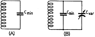
Fig. 1 - A - Circuit for fmax. B - Circuit
for fmin. Cmin is the total minimum circuit capacitance
which includes tube capacitances, minimum capacitance of the tuning condenser and
capacitance introduced by sockets and wiring as well as the distributed capacitance
of the coil. Cvar is the variable part of the tuning-condenser capacitance
(maximum minus minimum).
By Jack Najork, W2HNH
This article discusses a well-known but seldom-appreciated simple relationship
between frequency and circuit capacitance. It has the advantage over many radio
calculations in that it takes less time to work out the formula than it does to
arrive at the answer by the "cut-and-try" method.
One of the most useful formulas, and at the same time one most neglected by hams
who build or alter their own gear, is the simple mathematical relationship between
a change in the frequency of a tuned circuit, such as indicated in Fig. 1,
and the change in capacitance which causes it. Its most common application is in
the determination of capacitance values in bandspread or other tuning-range problems
in receivers or VFOs. It shows the frequency range that any variable condenser will
cover or, conversely, the variable capacitance necessary to cover a desired frequency
range.
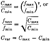
The relationship is expressed by

In other words, it always takes a capacitance ratio of the square of the frequency
ratio to cover the desired frequency range. If the frequency ratio, maximum to minimum,
is 2 to 1, the required capacitance range to cover it is 4 to 1; if the frequency
range is 3 to 1, the capacitance range must be 9 to 1, etc. And, of course, the
converse is true - the frequency range that a variable condenser will cover is the
square root of the capacitance ratio, i.e., a capacitance range of 4 to 1 produces
a frequency change of 2 to 1. Example:
Desired frequency range - 3500 kc. to 4000 kc.
Minimum circuit capacitance - 30 μμfd.
Frequency ratio = 4000/3500 = 1.143
1.1432 = 1.3
Therefore the capacitance change to tune over this band must be in the
ratio of 1.3 to 1. Since the minimum circuit capacitance with the condenser set
at zero is given as 30 μμfd., the maximum must be (1.3) (30) = 39 μμfd.
The difference between maximum and minimum, 9 μμfd., is the required variation.
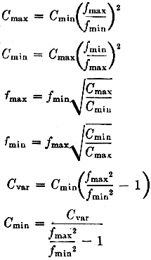
The formula can be twisted around, of course, to give any one of the desired
values by substituting known values for the other three factors.

In all of the foregoing, Cmin is the minimum circuit capacitance with
the variable condenser set at zero, Cmax the total circuit capacitance
with the variable in full, fmax and fmin
respectively the highest and lowest frequencies to which the circuit tunes and Cvar
the variation in capacitance in the tuning condenser. Cmin, of course,
includes any fixed capacitance that may be used in the circuit either for bandspread
or to obtain a high-Q circuit such as in VFOs. Of course fmin
and fmax, and Cmin, Cmax and Cvar,
should be in the same units, i.e., kc. or Mc. for f and μd. or μμfd.
for C.
In practical application it should be recognized that the variation in capacitance
that may be expected from a variable condenser is not the rated maximum capacitance
shown in the catalogues; it is the difference between the condenser's maximum and
minimum capacitance. A typical small 100-μμfd. variable may have a minimum
capacitance of 10 μμfd. making the variation only 90 μμfd. This minimum
as well as any capacitance introduced by mounting the condenser close to grounded
metal must be included in the minimum circuit capacitance, Cmin. This
minimum circuit capacitance usually is the only factor that is not readily determined
and since it may run as high as 50 to 75 μμfd. when capacitance coupling is
used between tetrode or pentode stages, especially when the condenser is mounted
close to the chassis, it isn't something that can be neglected entirely without
introducing considerable error in the calculations. In many cases, however, it is
possible to estimate the total minimum capacitance with an accuracy sufficient for
the purpose. In the case of capacitance coupling between stages, the output capacitance
of the driving tube and the input capacitance of the driven tube are in parallel
with the tank coil and therefore form part of the minimum circuit capacitance. The
values for any particular combination of tubes may be made up from the information
given in tube manuals.1 Variable-condenser minimum capacitances also
are usually shown in the manufacturer's catalogue.
Mounting a midget-type condenser on metal in the usual manner introduces a stray
capacitance between stator and ground equivalent to from 2 to 4 times the condenser's
rated minimum capacitance. This must be added to the circuit minimum although it
does not alter the amount of capacitance variation to any appreciable degree. Socket,
wiring, and coil capacitances may add another 10 to 20 μμfd. If the circuit
minimum is to be held down, the condenser in particular must be well spaced from
grounded metal chassis and shields.
The inductance required to go with the condenser may be determined from the following
formula:

where the frequency is in Mc., the capacitance in μμfd. and the inductance
in μh. Coil dimensions to give the calculated inductance may be selected from
published tables or the ARRL Lightning Calculator.
1 See p. 22, February, 1947. QST, for popular .audio-receiving-tube
capacitances.
Posted May 4, 2022
(updated from original post on 7/11/2016)
|


