|
|||||||||||||
 |
|||||||||||||
Panoramic Reception
|
|||||||||||||
"Technically, panoramic reception is defined as the simultaneous visual reception of a multiplicity of radio signals over a broad band of frequencies. In addition, panoramic reception provides an indication of the frequency, type and strength of signals picked up by the receiver. Deflections or "peaks" appearing as inverted "V"s on the screen of a cathode-ray tube." It is the kind of display that radar operators at Pearl Harbor were using when they mistook a wave of incoming Japanese bombers for a squadron of B-17s from the mainland. The panoramic receiver is not a wartime development, experimental models having been produced just prior to the outbreak of war. However, the many uses to which it has been put have demonstrated that the panoramic idea, particularly in the form of adaptors which may be connected to any receiver, is going to be very important and useful in the ham station of the future. In simple language this article reviews the general principles upon which the panoramic system is based and includes also a picture of the many ways in which it may serve the operator of a postwar amateur station. Panoramic Reception A Review of Its Principles in Simple Language
Fig. 1 - Typical signal patterns on the screen of the cathode-ray tube of the panoramic receiver. The peaks a and b indicate a c.w. signal or unmodulated carrier. The closed baseline of c indicates a rapidly keyed signal, while d's irregular shape identifies it as a modulated carrier. By Harvey Pollack,* W2HDL * Engineering Dept., Panoramic Radio Corporation. At a desolate, lonely post in the heart of the Allied lines in Burma, a Marine radio operator was grimly monitoring the bands used by the Japs for field orders. Before him were several communications receivers, each surmounted by a smaller cabinet containing a cathode-ray tube. His alert glance shifted from one to another of the fluorescent screens while he continually checked the frequency sheet used by the various Allied mobile and fixed transmitters in the area. The constantly shifting pattern of radiance was so familiar to his trained eye that only cursory and occasional corroborations were necessary; he knew almost instinctively that every station on the air was that of a friendly post. Suddenly, and without warning, a small peak appeared on one of the screens where none had existed before. It stood out like the shoe-button eye of a snow man. "Japs!" muttered the operator. "And mobile, too. - Look at that peak grow! Only thing that could come that fast is a flight of planes." Just as suddenly the peak winked out and the scene was restored to its former serenity. But the cat was out of the bag. The operator reached for the land-line transmitter and spoke a few clipped words into the mouthpiece. Almost instantly, at far-flung and widely separated aircraft installations, a sharp alert was sounded as the men took their stations. Long before the Japs came within striking distance, the Allied fighters met them head on. The Japs never had a chance.
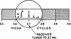
Fig. 2 - Graphic representation of the 3.5.Mc. amateur band with the panoramic adaptor sweeping the 3.6 to 3.8·Mc. section. The receiver is tuned to 3.7 Mc.
Fig. 3 - This is the same as Fig. 2 except that the receiver is now tuned to 3.6 Mc., the panoramic sweep now covering a range of 3.5 to 3.7 Mc.
Fig. 4 - Sketches illustrating how "resolution" may be improved by decreasing the sweep width. A indicates two signals very close together in frequency with a wide sweep band, while B shows how the same two signals are separated when the sweep band is reduced. What the Panoramic Receiver Tells Us The cathode-ray unit which makes such feats and many others possible is the panoramic adaptor which may be added to almost any type of receiver. Technically, panoramic reception is defined as the simultaneous visual reception of a multiplicity of radio signals over a broad band of frequencies. In addition, panoramic reception provides an indication of the frequency, type and strength of signals picked up by the receiver. Deflections or "peaks" appearing as inverted "V"s on the screen of a cathode-ray tube, as shown in Fig. 1, are indicative of the presence of signals. The character of each individual deflection tells its own story. For instance, in Fig. 1, a is a signal of constant amplitude indicating a steady carrier, while b is a nonvarying signal whose strength is about twice that of a. The signal indication at c is a peak which appears and disappears so rapidly that the base line appears closed beneath the deflection. This type of trace is produced by a very rapidly keyed c.w. signal. With slower keying the base line would appear open. Incidentally, if the keying is sufficiently slow the code can be read directly from the screen, like a blinker, after a little practice. The signal at d is composed of separate parts. The smaller peaks are produced by the sidebands of a modulated carrier, while the high center peak is produced by the carrier itself. Hence, this is the picture of a 'phone station. More often the side-bands will not be visible as separate deflections, a 'phone station trace being recognizable rather by a deflection which tends to vary in amplitude between the high center peak and the low center peak. The various frequencies shown may be compared with reference to each other or to the calibrated dial of the receiver. As an illustration, imagine that the receiver dial reads 5000 kc. Signal c, the c.w. signal discussed previously, appears immediately above zero on the scale. This scale reading indicates that the frequency of the signal is that indicated on the dial of the receiver; in other words, 5000 kc. Another way of saying the same thing is that the frequency difference between the receiver dial reading and the signal appearing over the center of the scale marking is zero. It follows from this that signal a is 100 kc. lower than signal c, or 4900 kc., while signal b is approximately 65 kc. lower than signal c, or 4935 kc. Hence, while signal c is heard on the receiver's normal output circuit, the other signals will be seen distributed as shown in the diagram. They will not be heard in the headphones, however, unless they happen to be close enough to c in frequency to be within the receiver's normal band of acceptance. Application to Amateur Bands For the sake of clarity, let us choose the 3.5- Mc amateur band for our discussion. This band extends from 3.5 Mc, to 4.0 Mc. and is shown graphically in Fig. 2. Now let us say that the receiver has been equipped with a panoramic adaptor which covers a maximum bandwidth of 200 kc. and that the receiver has been tuned to 3.7 Mc. All of the signals between 3.6 and 3.8 Mc. will be visible on the screen of the cathode-ray tube in the adaptor. The signal heard on the headphones will appear at the center of the screen as signal c. Now to listen to signal a, the receiver would have to be tuned to a lower frequency. As the receiver ·tuning is shifted, all of the peaks will move to the right across the screen until signal a is heard. At that point, a will appear centered on the screen as shown in Fig. 3. Signal c now has moved to the right of the screen and is visible but no longer audible in the headphones; b has passed through the center of the screen and might have been heard for an instant as it passed the center point of the screen. At the same time, new signals, d, e and f. which were not present previously now have made an appearance at the left side of the screen since the 200-kc. acceptance band has been shifted lower in frequency. Because the signals in this part of the band all are c.w., the deflections will appear and disappear in accordance with the keying. Should we now tune to the 'phone band the signals will appear as peaks pulsating in amplitude. This effect, as explained previously, is caused by the modulation. Sweep Width Another feature of an adaptor of this type is that the number of kilocycles visible at any time (sweep width) is under the direct control of the operator and may be reduced to any lesser value all the way down to zero if so desired. This control provides the operator with a visual selectivity control of the most flexible variety. As the sweep width is reduced, the resolution constantly improves. The term "resolution" is used here in the same sense as the word "selectivity" is used in discussing the frequency discrimination of receivers. Fig. 4 should help to illustrate this point. Two signals differing in frequency by 3 kc., let us say, will present the appearance shown in Fig. 4-A if the sweep width control is set at its maximum point. Now, as this control is backed off, the signals will appear to separate and at about 20 percent of maximum they will appear somewhat as presented in Fig. 4-B. This increase in visual selectivity may be carried still further by a greater reduction in sweep width. Not only does this feature permit visual inspection of signals which otherwise might interfere with each other, but also it makes possible the analysis of signals which are heterodyning one another. If we should be in the middle of a QSO when QRM starts to wash it out, a quick reduction in sweep width will disclose the side (high- or low-frequency) where the heterodyne modulation is taking place. A break-in flash to the other end - such as "shift two or three kc. higher" - will suffice to shift the QSO to clearer channels. Superheterodyne Fundamentals For the benefit of those who have permitted themselves to become rusty in elementary super-het-receiver theory, let us first review the principles upon which this type of receiver is based. Let us assume that a radio signal whose frequency is 100 kc, is to be received. Referring to Fig. 5, the 1000-kc. signal is fed into a tuned stage called the converter. At the same time the h.f. oscillator of the converter feeds a signal of 1400 kc. into the mixer section. When these signals are combined in the mixer, a new frequency representing the difference between the two original frequencies appears in the output. In this case the difference frequency (or intermediate frequency) is 400 kc. Of course, the original frequencies are still present, plus a fourth frequency equal to the sum of the original frequencies, but the tuning of the following i.f. amplifier is so sharp that only the 400-kc. signal is permitted passage. Following the highly selective intermediate-frequency amplifier, the signal is detected or demodulated, the modulation being amplified through the audio amplifier to a sufficiently high level to operate a speaker or headphones . Thus we have: Oscillator frequency ....................................................... 1400 kc. Signal frequency ............................................................ 1000 kc. Intermediate frequency ................................................... 400 kc. Now, should we desire to listen to a station at 1300 kc., we would rotate the tuning-condenser knob to the new position. Since a ganged tuning condenser is usually employed, in so doing we have changed both the frequency to which the converter is tuned and the oscillator frequency and we now have: Oscillator frequency ....................................................... 1700 kc. Signal frequency ............................................................ 1300 kc. Intermediate frequency ................................................... 400 kc. It will be noted that the i.f, has not changed because we have maintained a constant difference between the signal frequency and the oscillator frequency. Thus the tuning of the i.f. amplifier may be fixed for all signal frequencies so long as the oscillator frequency" tracks" 400 kc. higher (or lower if desired) in frequency than the frequency of the incoming signal. In this case, the i.f. amplifier is tuned to 400 kc. and left there. It is obvious that many signals differing quite widely in frequency are inducing their respective voltages in the antenna. Although the input circuit of the converter stage is tuned, its selectivity is so poor that signals differing by several hundred kilocycles from the one to which the receiver is tuned will appear at the grid of the converter tube, with only slight attenuation below that of the signal to which the receiver is tuned. Thus, with the response characteristic shown in Fig. 5, the amplitudes of signals at 900 and 100 kc. are only slightly below the amplitude of the signal at 1000 kc. to which the. receiver is tuned.
Fig. 5 - Block diagram of the various units comprising a superheterodyne receiver with panoramic adaptor. The accompanying graphs serve to illustrate the tuning characteristics of the principal units of the system. Starting with the assumption that several signals of equal strength reach the antenna, the signal to which the converter is tuned will be the strongest, as we have seen, while the others which are off resonance will fall off in relative strength to a degree depending upon the frequency separation from the frequency to which the converter input is tuned. Although it would be impossible to receive these signals simultaneously by the usual aural method without interference, we shall see that this can be done visually by panoramic reception. The Panoramic Adaptor A small portion of the voltage developed by each of these input signals is taken from the output of the converter and fed into the r.f. amplifier of the panoramic adaptor which is broadly tuned with the i.f. of the receiver (400 kc.) as its center frequency. It will be noted from Fig. 5 that the input circuit of this stage is designed to have a response characteristic opposite to that of the input circuit of the receiver's converter stage, the ultimate effect being to compensate for the dropping off of signals off resonance in the converter stage, so that all signals of equal strength at the antenna again are essentially equal in strength at the grid of the adaptor r.f. stage. The signal from the r.f. stage is fed into a converter stage whose input circuit also is broadly tuned to accept all signals delivered to it by the r.f. stage with as little attenuation as possible. The local oscillator used in connection with this converter is normally tuned to a frequency 200 kc. higher (or lower) than the center frequency of the band accepted by the converter input circuit to produce an i.f. of 200 kc. However, the frequency to which this oscillator is tuned does not remain constant as it does in the receiver proper. Its tuning continually is varied or swept over a selected range of frequencies so that at some point in its excursion it mixes or beats with each one of the signals appearing at the input of the adaptor converter to produce the required i.f. of 200 kc. Thus when this oscillator's frequency is 500 kc., it beats with the 300-kc. signal to produce an i.f. of 200 kc. to which the following i.f. amplifier is sharply tuned. Similarly, when the oscillator's. frequency. is at the other end of its range, 700 kc., it beats with a 500-kc. signal again to produce an i.f. of 200 kc. Cathode-Ray Indicator The output of the adaptor's i.f. amplifier is rectified and the resulting d.c. voltage is applied to the vertical deflecting plates of the cathode-ray tube. We know that with no voltage on either vertical or horizontal deflecting plates the spot on the screen of the cathode-ray tube normally will be stationary at the center of the screen. If, however, a varying voltage is placed across the vertical deflecting plates, the spot will move in a vertical direction, forming a luminous line if the variations in voltage are sufficiently rapid to create persistence of vision. Therefore, if we were to tune the adaptor's oscillator to beat with one of the signals at the input of the adaptor, the out. put voltages of the rectifier following the i.f. amplifier would follow a curve similar to the response curve shown for the adaptor's i.f. amplifier in Fig. 5, and if this voltage is applied to the vertical deflecting plates of the cathode-ray tube, the spot will move upward from the center and then back to center as the beat between the oscillator and the signal approaches the i.f, of 200 kc. and then recedes after passing through maximum at 200 kc. If the tuning of the oscillator in this manner is done repeatedly and at a high rate of repetition, a vertical line would appear on the screen of the cathode-ray tube. Now, if at the same time a smoothly varying voltage is applied to the horizontal plates, the spot will move under the influence of a horizontal as well as a vertical force and the resulting path will resemble the i.f. response curve. Electronic Tuning In the panoramic adaptor, the tuning of the oscillator is not done manually, of course, but this is accomplished by a reactance modulator whose characteristics are such as to sweep the frequency of the oscillator back and forth over the proper range at a rate corresponding to the rate of oscillation of a second special oscillator called the b.t.o. (blocking-tube oscillator). Voltage from the b.t.o. also is fed to the horizontal deflecting plates of the cathode-ray tube so that the spot when no signal is present at the input of the adaptor is moved back and forth horizontally in synchronism with the sweeping of-the adaptor's converter oscillator. If signals are present at the input of the adaptor, they will cause vertical deflections whenever the oscillator's frequency is appropriate to produce the required 200-kc. i.f, and these signals will then be reproduced in succession as indicated in Fig. 5. Normally, the sweeping action is set at a repetition rate of about 30 cycles per second, any rate which will maintain persistence of vision being adequate. Since the signal to which the receiver is tuned corresponds to the center of the range being swept by the adaptor's oscillator, it follows that any peak appearing in the center of the screen is caused by the signal to which the receiver is tuned. Also, since the amount of vertical deflection for any given signal is proportional to its strength, strong signals will cause high peaks on the screen, while the peaks of weaker signals will be proportionately lower. Ham Applications It is not difficult to visualize many ways in which panoramic reception may be applied in postwar ham work. It is, of course; very easy to spot an unoccupied channel on the screen of the cathode-ray tube, and just as easy to watch the e.c.o. of the station's transmitter walk up to the vacant hole as the operator tunes it to the proper frequency. Not only is the lining up of stations in a spot-frequency net facilitated, but if net stations or stations in a "round-table" are operating on scattered frequencies, the control-station operator can keep tabs on all of them without disturbing the setting of his receiver. This sort of visual reception is valuable in many other practical operating tricks. By the pattern on the screen, it is possible to check percentage of modulation, comparative signal strength, carrier shift and other signal characteristics. With the sweep width reduced to zero, the panoramic receiver becomes an oscilloscope. With a calibrated scale on the screen accurate frequency checks may be made. While it is not probable that many operators could develop visual code-copying speed comparable with the speeds possible by ear, it should not be difficult for any ham to develop his eye to the point where he readily could recognize such things as the "CQ SS" of a Sweepstakes contest! |
|||||||||||||
 |
|||||||||||||
|
|||||||||||||


|
||||||||||||||||||||||||||||||||||||


