January 1967 QST
 Table
of Contents Table
of Contents
Wax nostalgic about and learn from the history of early electronics. See articles
from
QST, published December 1915 - present (visit ARRL
for info). All copyrights hereby acknowledged.
|
The American Radio Relay League (ARRL) has
been on the cutting edge of communications technology since its founding in 1914
by Hiram Percy Maxim. Then, as now, many of the nation's top electronics
and antennas experts have been intimately involved in the design, testing, operating,
and regulating aspects of radio systems. Over time radar, software, and computer
technologies have been added to the mix of specialties as have program management,
field deployment and fixed station logistics, facilities management, and many other
talents. A natural result of all the human capability affiliated with the ARRL is
the collective personal investment in keeping flagship station W1AW as a shining
example of what amateurs (hobbyists) can achieve. This article from a 1967 issue of
QST magazine reports on how W1AW was outfitted with state-of-the-art equipment
and support equipment. At the end, I posted a couple photos of W1AW in 2013, with
hyperlinks to the ARRL website sources.New Look at W1AW
W1AW and the Hq. building are situated on a 7-acre site with plenty of room for
antennas. Three self-standing 60-foot steel towers (two are visible on the front
cover) support 3-element Yagi beams for 20, 15, and 10 meters. A 6-meter omnidirectional
antenna shares one tower with the 15-meter beam and a 2-meter omnidirectional antenna
is on another tower with the 10-meter beam. For 40, 80, and 160 meters, half-wave
horizontal wires are used. The 80 and 40 meter doublets are center fed: the 160-meter
doublet is end fed. Feed lines for all the antennas are situated underground and,
on 40, and 160 meters, the underground coax terminate at remotely controlled antenna
couplers located on the ground directly below the antenna feed points. Open-wire
feeders connect the antennas to the tuners.
The Maxim Memorial Station, W1AW, faces the new Headquarters Building at 225
Main St. in Newington, Conn. Recently, the station was given an overhaul with new
equipment, furnishings, and antennas. You've seen a picture of the exterior on this
month's cover. Here are a few shots taken inside the building, to show you some
of the "new look."
|

"Old Betsy," W1AW's 1920 spark transmitter, is on display in
the foyer.

The master control console contains several receivers, signal
monitors, transmitter exciters, punched-tape keyer (for code practice and bulletins)
and operating accessories. Against the wall at the left is the RTTY position. The
rack at the right is a back-up transmitter and RTTY transmitter.

Another view of the transmitter racks taken from behind the visitor's
operating position.

In case of a power failure, this 20-kw. 220-volt emergency generator
located in W1AW's basement can handle the entire load at W1AW including light, heat
and communications. The unit is electrically started and the engine is fueled by
propane gas. Notice the emergency lighting on the wall at the upper left. This light
(and others located throughout the building) come on automatically with loss of
power.
|
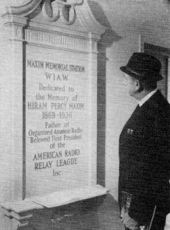
Visitors are always welcome at the station and upon entering
are requested to sign the guest log. (Here is the
Hiram Percy Maxim Memorial plaque now.)
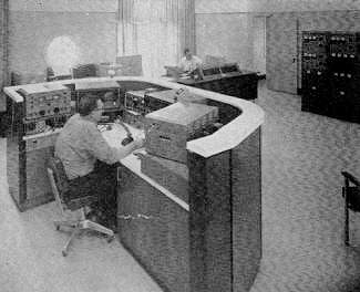
Another view of the console which faces the transmitter racks
(right) and the visitor's operating position.

Close-up view of the transmitter racks. In the top two rows are
some of the 1-kw. finals for 80 through 10 meters (two more to be added.) Other
equipment includes a 50-watt 160-meter transmitter, 200-watt 2-meter transmitter,
200-watt 6-meter transmitter, antenna patch panel, and converter to change the 3
Mc. signal from the console exciter to the various amateur bands, 80 through 10
meters.

The W1AW workshop is well equipped for emergency repairs or general
maintenance.
|
Now that you have had a chance to browse around the interior of W1AW, here are
a few additional details about the station. The operating center of the station
is the master console. Located here, along with the usual operating position accessories,
are auxiliary receivers and signal monitors. The station v.f.o./exciter is positioned
here and generates a basic 3-Mc. s.s.b., c.w., a.m., or RTTY signal, which is then
fed to the transmitter racks. A series of converters heterodynes the 3-Mc. signal
to the desired amateur band (80 through 10 meters) where it is amplified in the
appropriate 1-kw. linear amplifier. The racks also contain s.w.r. bridges and indicators
for each antenna system, along with controls for remotely tuning antenna couplers
where applicable. There is an antenna patch panel for switching the various transmitters
and receivers in the station to the desired antenna.
For code practice or bulletins, an RTTY tape, which has been previously cut at
the station, is fed into an RTTY-to-Morse converter, which transforms the RTTY characters
on the tape to dots and dashes and then keys the transmitters. Of course, this same
tape is used to key the RTTY equipment, too.
Page 92 shows the station schedule, and visitors are always welcome. Meanwhile,
make use of the varied services provided by the Maxim Memorial Station - daily sessions
of code practice, news bulletins, frequency-measuring tests, and general operation.
There's a lot more to see here at W1AW. Why don't you drop in and see it for
yourself?
Now, here are a few photos of today's W1AW
Posted May 17, 2023
(updated from original post on 12/12/2013
|


