|
|||||||||||||
 |
|||||||||||||
The Fixed "Rotary" Beam Antenna
|
|||||||||||||
On a fairly regular occasion someone will write to one of the QST magazine columnists or post on a forum asking about information on a particular antenna configuration he recalled seeing printed many moons ago, but can no longer find anything on it. Fortunately, the columnists are guys who have been in the Ham game for a many decades and not only remember what the writer references, but knows where to dig out the original info. Even with the plethora of resources available on the Web, some things still cannot be found because nobody yet has posted it. That is one of my prime motivations for doing what I do - that is to help make useful data available. That is the reason I also scan and post schematics and service pages for vintage radios. The Fixed "Rotary" Beam Antenna
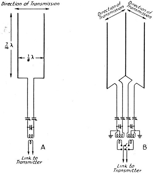
Fig. 1 - The fundamental" pitchfork" antenna system, such as is used at W2USA, is shown at A. Two pitchfork antennas can be combined, as at B, to give coverage in directions along two lines at right angles to each other. The elements are vertical in both cases. Variable Directivity With Fixed Antennas By Arthur H. Lynch* W2DKJ Although the antenna systems described in this story are not exactly brand new, many of the ideas regarding installation and operation are, and you're bound to garner food for thought from these pages. The amateur with a lack of roof space will find it particularly to his liking. It all came about in the following manner. Our good friend, W2BKX, bought himself a house in Garden City, L. I., and restrictions regarding antennas are just a little bit tough in that town. George, who had been doing some excellent work with low power on 10 meters from his location on the roof of a lofty apartment in New York City, wanted to duplicate the performance in his new home. Lacking the height of his old location, we knew it would be necessary to go to some form of beam. The usual "hay rack," suitable for a three- or four-element horizontal rotary, was out of the question. Whenever occasions like this arise we can't avoid remembering the shock we all got from the performance of the vertical 20-meter "pitch-fork" antenna that was used at W2USA for so long, before the full-wave vertical rotary was erected. The former, which was the same as the antenna of Fig. 1A, was set right on the roof of the building. The roof was made of metallized roofing paper, and it furnished a very effective counterpoise. The beam, made of Premax aluminum units, was set up along an east-west line, and it gave us a grand signal in those directions, but we were surprised to find that the beam was not too sharp and that we were getting out in nearly all directions except at exactly right angles to a line through the elements. That experience, coupled with the reports of others who have tried the three-vertical system1 for securing transmission in all directions, led us to the conclusion that more might be accomplished with the method than had been considered previously. Instead of confining the beam to single-band operation we decided, in George's case, to try the same arrangement on all the bands which he would desire to work. Since the lowest-frequency band he uses is 28 Mc., the 10-meter band was used as the starting point for calculations. The use of tuned lines was dictated by the multi-band operation, but this has the advantage that the system can even be used on the next lower frequency band with, of course, some compromise in performance. However, it should be remembered that we are attempting to get the most out of the least and, while it is recognized that it is possible to design an antenna with the same number of elements which will do a better job in anyone direction and on anyone band, we believe that the many uses to which this system can be put warrants its consideration by anyone with limited antenna space.
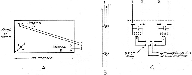
Fig. 2 - If room is available, two pitchfork antennas can provide good coverage by separating them on the house-top, as shown at A. Suggested construction of the feed line is illustrated at B, and the antenna coupling detail is shown at C.
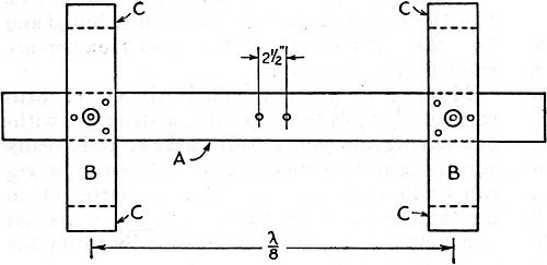
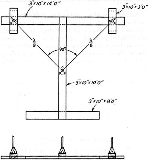
Fig. 3 - Plan view of the supporting framework of the 14 Mc. pitchfork antenna at W2USA. The members are made of 3-inch by 10-inch stock; A is 10 feet long, B is 4 feet long, and C is 5 inches long. For 28 Mc., the members can be 2-inch by 4-inch stock, with A 6 feet long, B 2 feet long, and C 4 inches long. In either case, the supports are held fast by sandbags laid on them. The pitchfork antenna has, of course, a null along the line at right angles to the plane of the elements. This null can be overcome by using a third element as shown in Fig. 1B. By selecting the proper pair of elements, the signal can be radiated most effectively in any desired direction while still retaining the gain of the system. Naturally, either pair of elements can be used with equal effectiveness along a line making an angle of 45° with the line of the plane of the elements, but in any other direction a particular pair will be more effective. If room is available for the erection of two separate beams a half wavelength or more apart and at right angles to each other, it would be well worthwhile, and the directional pattern would be nearer the pure theoretical one than is possible with the compromise system using three elements. Many of the houses in the larger cities have roof space of 25 by 40 feet or more, which is plenty of room for the use of two pitchfork antennas, as shown in Fig. 2. When less space is available, it is necessary to go to the system shown in Fig. 1 In W2BKX's case it was necessary to use the compact system using three elements (Fig. 1B). Since the mechanical arrangement used on that job may be of help to others, it is given in more than ordinary detail later in this story. At first, consideration was given to the possibility of using a single antenna coil for each band and placing the antenna relay at the ends of the four lead-in wires, using link coupling to the antenna coil from the final tank and tuning the feed line with two series condensers and a third condenser in parallel. However, the final arrangement shown in Fig. 2C is very much more effective and easy to control, although it requires a bit more apparatus. In addition to providing suitable operation on anyone band it allows the use of both antennas at the same time, for general coverage use when calling CQ. For convenience, the two transmission lines are carried by the same separators. Old-fashioned cage antenna spreaders (which are still available in some radio stores) can be used, or curtain rings of celluloid, Bakelite or well-varnished wood can be drilled to take the wires. Whether the triangular set-up with three vertical elements or the two spaced pitchfork antennas are used has no bearing on the feed system or the tuning of the two antennas and, for this reason, the two cases have not been treated separately. When two separate pitchforks are to be used on only one band, a quarter-wave matching section and any type of non-resonant line is probably the best method of feed - the tuned line is described in this case because we were interested in multi-band operation. Mechanical Details Where two elements are to be used in a single pitchfork set-up, which is all that is required in many locations, it may be well worthwhile to take a page from the book of construction of W2USA and use the simple framework shown in Fig. 3. If two separate pairs of verticals are used, two similar frames can be used. This form of construction makes the use of nails, lag-bolts or other fastening directly to the roof unnecessary. Sand bags will do very well for anchors. If a coarse bag is used, it will be found advisable to use coarse sand. In some instances, we have found it desirable to add a little cement, so that the bags will take the form of the supports and harden in that shape.
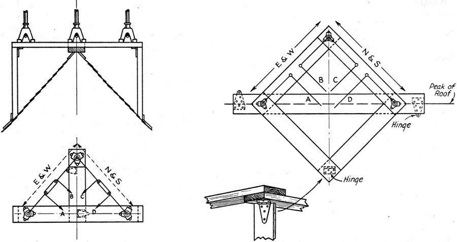
Fig. 4 - Plan view of the supporting platform for a three-element 14-Mc. fixed" rotary" beam set on a flat roof. The frame can be held in place by sandbags. Where three verticals are to be used to provide the" rotary" effect and they are to be set up on a flat roof, the layout shown in Fig. 4 will be found desirable. Where 20 meters is the" fundamental" frequency of the system, the vertical elements will be approximately 29 feet high, and the supporting structure should be reasonably heavy. Planks of warp-free, well-dried, solid wood, 3 inches thick and 10 inches wide, are suitable for this use. The lengths are indicated in the drawing. Where 10 meters is to be the lowest fundamental frequency, the vertical elements will be of lighter material, less than 15 feet high and only 4 feet 4 inches apart. For that reason regular 2 by 4 stock, half the lengths indicated in Fig. 3, will do very nicely on 28 Mc. It will be noted that plenty of room has been provided for the use of sandbags, since their liberal use may be warranted if the array is going to be subjected to high winds. The blocks at the ends of the small members are made of the same lumber which is used for the other members and provide equalization for those portions of the structure which are above roof level. Hinges Where we have a flat roof to deal with, the problem of the fixed "rotary" beam, except for the manner of running the transmission lines away from the structure, is relatively easy. However, where we have to set one of the three vertical assemblies on a peaked roof, we have a horse of another color. In the accompanying drawings, Figs. 5 and 6, two alternative methods are shown. In the side elevation, it can be seen how the weight of the assembly is distributed and how the outside ends of the cross member are supported by the roof. Most of us are not sufficiently clever with carpenter's tools to make such a structure without having the joints badly askew. It is really surprising to find what a great help strap hinges can be in such circumstances. A quarter of an inch here or there or a badly cut angle on the end of a supporting strut would ordinarily throw the whole beam out of kilter, while hinges, used as indicated in the top view, permit us to do the trick quite easily. Before attaching the hinges to the various members, we should be sure to place them so that they will ride over the centers of the roof studs, where the weight will be carried without the possibility of punching a hole through the shingles or other roofing material. Another important advantage resulting from the use of hinges for this purpose is that it is difficult to make screws or bolts hold when we put them through one surface into the butt-end of another member, while using the hinges makes it possible to set the screws into side surfaces at all times, with better distribution of the stresses and providing greater strength as well as ease of assembly.
Fig. 5. - Two different methods for mounting the three-element fixed" rotary" on the peak of a roof. The use of hinges offsets any minor lack of carpentry skill.
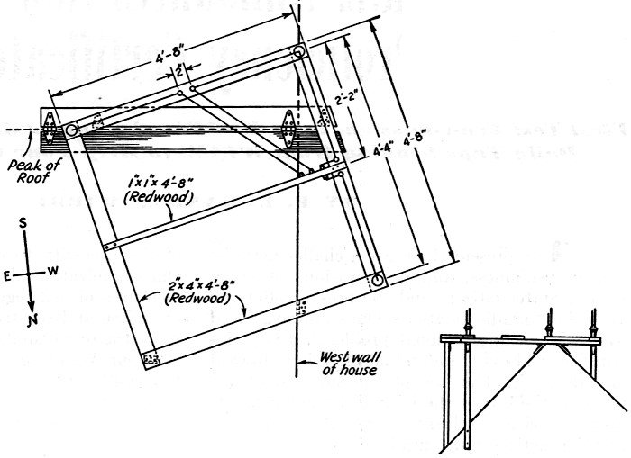
Fig. 6 - The framework used to support the three-element 29·Mc. antenna at W2BKX' The small side view more clearly shows how the hinges simplify construction. The assembly which we designed for use at W2BKX's new location is a simple square made of two by four stock. It wasn't the easiest thing in the world to set it up, because the house doesn't aim just right to get the proper directions for the beam without putting the supporting frame at a cock-eyed angle with relation to the roof lines. Then, too, the roof is slate (and, besides, it's George's new house), so we couldn't go banging nails here and there, as we have been accused of doing on other occasions. (The story is much exaggerated and we have not done any such thing. The bedroom ceiling fell down as the result of what we know was a poor roofing job, but which we can never prove was not the direct result of our excursions about the roof.) Fig. 6 gives the details of the assembly, and it will be seen that we have again gone very strongly for the use of hinges. Even a poor carpenter can do a fairly respectable job of setting up such an assembly by using hinges generously and a spirit-level frequently. The 6-foot planks of 2 by 6 were first laid side by side along the peak of the roof, after they had been held together by a couple of hinges. That gave us the support for most of the weight and the rest was relatively easy. More hinges, attached to the ends of a pair of 2 by 4's which were in turn attached to the outside west wall of the house, gave us the bracing for the ends, and other hinges held the remainder of the framework to the two long planks. The sandbag draped over the east end of the whole job goes a long way toward holding things under control, even in a high wind. In this case, the matter of bringing the transmission lines down has been made relatively simple because they drop in a straight line to a point outside the radio room window. Insulators, suitably disposed along the small cross strut give the lines a good start. The feed line is made up as previously described (Fig. 2-B), and is run down the side of the house. A bracket outside the window supports the other end of the line. The Counterpoise Reference has been made to the effectiveness of beams of this nature being improved when it is possible for us to erect them adjacent to flat metal roofs, where the roofing acts as a counterpoise. However, very much the same effect can be had, even when we are located in a frame house having a shingle or other form of non-metallic roof. If it is possible to get into the attic, it is only necessary to procure some metallized insulation paper, which carries the trade name "Reynold's Metallation," and tack it up on the rafters. It comes in two kinds. One has metal on only one side and the other type has aluminum foil on both sides. We "got it wholesale" so nothing was too good and, instead of providing ourselves with the usual size counterpoise, we covered the whole inside of the attic, using the bi-metal type of paper, of course. It works very well for what we set out to do with it, and it really does hold the heat out in summer and in during the winter. It brings another blessing by carrying any possible leaks in the roof to some portion which is not graced by some form of antenna support. So, if you think a counterpoise would be of any advantage to you, it might be a good idea to "sell" the family the idea of insulating the attic. But be very careful that they don't hook you with the idea of using some form of non-metallic wall board and then let you have the job of finishing off the attic, which has been under consideration for so long, leaving you without your counterpoise. * Managing Director, W2USA Radio Club, World's Fair, New York 1 Lynch, "Feeding Vertical Antennas," QST, Jan., 1939. |
|||||||||||||
 |
|||||||||||||
|
|||||||||||||

|
||||||||||||||||||||||||||||||||||||


