|
October 1947 QST
 Table of Contents Table of Contents
Wax nostalgic about and learn from the history of early electronics. See articles
from
QST, published December 1915 - present (visit ARRL
for info). All copyrights hereby acknowledged.
|
"QRM" is the Q-code in Ham-speak for
unwelcomed manmade inband electrical interference. Interference is not just random
signals like noise from motor brush arcing, intermittent electric distribution system
connections or inter-conductor arcing, etc. An improperly tuned or ineffectively
filtered radio transmission, or EM energy leaking from a poorly shielded electronic
device is also QRM. I distinguish such noise as unwelcomed because what might be
considered as noise by one person could be a desired signal by another. "QRN" stands
for electrical noise generated in nature such as lightning bolts, solar storms,
or even, as discovered by Drs. Arno Penzias and Robert Wilson, the 160 GHz
Cosmic
Microwave Background (CMB) radiation that emanates from all regions of the sky.
A mnemonic for remembering which Q-code is which is the trailing "M" for manmade
and "N" for natural.
The interference elimination scheme described here works by using a local oscillator
to generating a second, lower intermediate frequency (IF) that then is fed through
a narrow filter on either the upper or lower sideband, thus eliminating nearby interferers.
It is fundamentally a dual conversion receiver, which is still used when suppressing
strong multi-tone signals required - particularly where purely analog signal are
used (hence, not much opportunity for post-detection signal processing).
Exit Heterodyne QRM
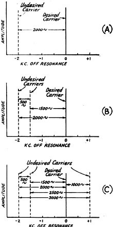
Fig. 1 - Audio beats produced by rectification of two or
more carriers. When four carriers are present, as in C, there are six beat frequencies.
Removing the two carriers on the lower side of the desired carrier, before detection,
will eliminate all but the heat between the desired carrier and the one on the high-frequency
side.
Selectable Single-Sideband Reception Up-to-Date
By J. L. A. McLaughlin
Here is a simplified and improved version of the receiving system first introduced
in QST just before the war. A thorough trial in wartime radio intelligence work
proved the worth of the system - a system that can go a long way toward eliminating
QRM in both phone and c.w. reception.
The need for improved means of receiving signals through heterodyne beat-note
interference has in the last few years become increasingly apparent.
During the war the writer designed and built for the Federal Communications Commission
and the Office of Strategic Services a receiving system that enabled them to copy
phone and c.w. transmissions through terrific heterodyne QRM that made reception
hopelessly impossible on the best. conventional receivers.
The FCC first employed this communications aid as far back as the summer of 1941.
The June, 1941, issue of QST contained an article by this author describing this
communications development.1 Mr. George Sterling, then chief of the Radio
Intelligence Division of the FCC, was quick to recognize the importance of this
invention2 to the highly specialized work in which the Commission was
engaged. The Commission immediately purchased the original development model and
subsequently ordered units for all primary monitoring stations throughout the country.
Because of Mr. Sterling's foresightedness, when war came one Government agency,
at least, was capable of carrying on radio intelligence work in the face of malicious
or accidental interference. When the communications division of the OSS was set
up, shortly after the start of the war, it, too, promptly ordered similar equipment
for its services.
The first war model supplied the OSS and the FCC was similar to the early models
used by the FCC. Later, a second war model was designed for the OSS; it was a decided
improvement over earlier models both in performance and design. It was more compact,
for one thing, and it was self-contained and could be connected to any of the standard
communications receivers in use by the OSS, without modification or circuit changes
in the attached receiver. Because this later model lends itself more to present-day
amateur requirements, this article will be devoted to an explanation of its performance
characteristics in the presence of strong heterodyne interference.
Heterodynes
How this new heterodyne-eliminating receiver operates will perhaps be made clearer
if we take up first the causes of beat-note interference and the inherent weakness
of todays communications receivers in the presence of such interference.
The single heterodyne audio beat note, the product of one off-frequency carrier
boating with the carrier of the desired signal, is well understood, but the audio
beats produced by multiple off-frequency carriers are not clear to many.
Fig. 1 will help to form a picture of just what takes place after rectification
of two or more carriers. Fig. 1-C indicates that when four carriers are present
six principal audio beat notes are produced by rectification.
The removal of one heterodyne beat note can be achieved either before or after
rectification by some form of phasing device; that is, some scheme capable of putting
a variable rejection notch in the response curve of either the i.f. or a.f. amplifiers.
Schemes such as these have been mentioned in the pages of QST by this and other
authors. The rejection of a single interfering carrier can be demonstrated quite
beautifully in the laboratory, but under normal communications operations, when
complex heterodynes are present, these systems fail to generate any great enthusiasm
in the operator. The reason for this coolness can be found in an inherent weakness
in all such devices - that is, in the presence of heterodyne interference the beat-note
tone seldom will give any clue as to whether or not it is being produced by only
two carriers, or by more than two. If there are more than two carriers present this
sort of rejector falls down. Instead of being an aid the adjustable rejection becomes
a nuisance, and distracts the operator's attention from the real job at hand - i.e.,
the message being received - and forces his attention on the beat notes.
It is obvious that to be useful under present-day crowded band conditions any
practical system of heterodyne elimination must first of all be rapid in operation,
suppressing all the interference that it is capable of suppressing under the particular
receiving conditions in a minimum of operating time. It must not introduce any new
operating techniques alien to the normal training of the operator - rather it must
permit the operator to concentrate on the' signal being received, not on the interference.
The system developed by this author (Fig. 2), which is the subject of this
article, satisfies these conditions. It is fast and effective, being semiautomatic
in eliminating multiple-heterodyne QRM both on 'phone mid c.w.
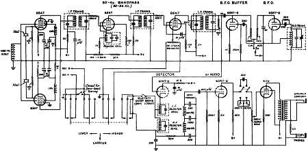
Fig. 2 - Circuit diagram of an adaptor unit for working
with a conventional communications receiver. The i.f. output from the receiver is
introduced to the two 6SA7 converter tubes at the left. The oscillator of "A" is
on 405 kc., and oscillator "B" is on 505 kc. Only one 6SA7 is in operation at any
time, as determined by the position of the switch. In either case the resultant
beat with the desired signal is 50 kc., which passes on through the 50-kc. bandpass
amplifier. However, the interference appears on the high-frequency side or the low-frequency
side of the 50-kc. signal, depending on its initial relation and which converter
tube is in use. The unsymmetrical 50-kc. channel has high attenuation for frequencies
below 50 kc. and rejects the interference and sideband on one side of the signal.
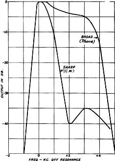
Fig. 3 - Selectivity curve of the 50-kc. i.f. amplifier
with and without the 52-kc. rejector circuit.
Operating Principles
The receiver is fundamentally a triple-detector superheterodyne. The desired
signal in the first i.f. system (455 kc.) is converted to a new intermediate frequency
of 50 kc. This 50-kc. i.f. system differs from the conventional in that the response
curve is unsymmetrical (Fig. 3). All frequencies below the carrier (50 kc.)
are greatly attenuated, giving the amplifier the characteristics of a high-pass
filter.
On 'phone reception this unsymmetrical selectivity of the 50-kc. i.f, system
permits single-sideband reception. Since both sidebands contain identical intelligence,
we can sacrifice the one containing the undesired signal without reduction of intelligibility
or naturalness.
The manner in which the desired single sideband is selected is as follows: Two
crystal-controlled oscillators are used, one ("A") on 405 kc. and the other ("B")
on 505 kc. Either will convert the 455-kc. carrier to 50 kc. Although the desired
carrier remains the same in both cases, all other frequencies converted will be
transposed when switching from oscillator "A" to oscillator "B." "A" converts the
455-kc. signal to 50 kc. and all the side frequencies in the same numerical order,
hence the upper single-sideband frequencies are selected in this case. Oscillator
"B" converts the 455-kc. signal to 50 kc. and inverts the numerical order of the
sideband frequencies, hence the lower sideband frequencies are selected in this
case.
Assuming that an undesired carrier happens to be 456 kc., "A" will convert this
"side" frequency of 456 kc. to 51 kc., and oscillator "B" will convert the same
frequency to 49 kc. In other words, we have here a system in which we can switch
undesired carriers from a frequency on one side of the desired carrier to a new
frequency on the other side. Since the 50-kc. i.f. is of the high-pass single-sideband
type, this switch permits placing the undesired carrier either in or out of the
passband frequencies. In the case of the 456-kc. interference, oscillator "B" would
be selected to eliminate the 1000-cycle beat note; "B" converts the signal to 49
kc., which frequency is attenuated 50 db. in the 50-kc. i.f. filter. If "A" had
been used instead, the undesired signal would have been converted to 51 kc., resulting
in no attenuation at all.
C. W. Reception
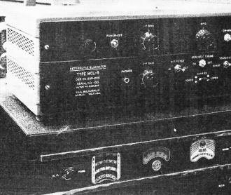
The heterodyne eliminator is a small unit that can easily be
set on top of a communications receiver. This model was built for the OSS for wartime
radio intelligence work.
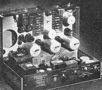
An inside view of the unit. The 50.kc. i.f. amplifier is mounted
under the hinged lid.
The selectable single-sideband system of heterodyne elimination is an obvious
improvement in the reception of 'phone signals. At first glance its value in c.w.
operation may not be so apparent. The improvements, though not obvious, are nevertheless
present. The unsymmetrical filter (50-kc. i.f.) cuts off very sharply at the edge
of the signal carrier's frequency; it is similar to a crystal filter with the rejection
notch set about 1000 cycles below resonance. It differs from the crystal curve,
however, in that it cuts off a wide band of frequencies rather than putting a notch
at one particular frequency in the resonance curve. By means of the sideband selector
switch we can flip an undesired carrier to the low-frequency side of the unsymmetrical
filter. It should be obvious that throwing a switch that removes a whole band of
frequencies is faster and easier to do than adjusting a critical phasing control,
as is the practice in crystal-filter operation.
The second point in favor of this system over the crystal filter is that the
objectionable" ping" of the high-Q crystal circuit is absent. A final improvement
in the reception of C.W. signals is achieved by use of a sharply-tuned 1000-cycle
filter in the audio circuit. This filter, together with the unsymmetrical response-curve
switching system, makes for very easy c.w. operation even in the presence of tough
QRM. In c. w. work the b.f.o. is left fixed at the correct frequency to produce
a 1000-cycle beat note with the desired signal. The operator merely tunes for maximum
signal strength.
Tuning the Carrier
A prime requisite of single-sideband 'phone operation is placing the desired
carrier correctly in the bandpass filter of the second i.f. In the model described
earlier a visual system of tuning was employed, using a tuning meter connected to
the output of a sharply-tuned 50-kc. amplifier.1
In the later system this extra equipment has been eliminated and an accurate
aural system substituted. The center position of the sideband selector switch is
marked "carrier." In this position oscillators "A" and "B" are both operating, and
the correct tuning is indicated aurally when the signal is tuned to zero beat with
itself. (The two i.f. signals produced by the beats between the desired carrier
and the two oscillators move in opposite directions as the receiver is tuned.) Further
help in aural carrier positioning is achieved by narrowing the bandwidth of the
high-pass filter in the "carrier" position of the switch. This bandwidth is made
only a few hundred cycles wide and peaked sharply at 50 kc. When the sideband control
switch is flipped either to the upper or lower sideband the original bandwidth of
the high-pass filter is restored and one oscillator is disconnected. This improved
aural tuning system permits normal tuning by ear of a 'phone signal in the presence
of extreme interference.
For c.w. reception as well as 'phone the FCC and the OSS found this system far
superior to the conventional communications receivers. These units made it possible
to copy signals through heterodyne interference that otherwise would have made them
unintelligible.
1 McLaughlin, "The Selectable Single-Sideband Receiving System," QST, June, 1941.
2 U. S. Patent No. 2,364,863.
Posted August 16
(updated from original post on 8/16/2016)
|


