|
|||||||||||||
 |
|||||||||||||
A Simple 5- and 10-Meter Transmitter |
|||||||||||||
A Simple 5- and 10-Meter Transmitter For Portable/Mobile and Home Station UseBy Wilbert L. Thompson*
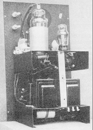
A 5 & 10 transmitter in a 7- by 9- by 15-inch cabinet, good for a 15- to 20-watt carrier. The two main dials control the oscillator and amplifier tuning, and below the dials can be seen jacks for metering the various cathode circuits. The two buttons directly below the dials are dial lamps used to indicate crystal current and filament "on".
A rear view of the transmitter shows the r.f. portion on the upper chassis and the modulator below. The construction is conventional throughout. With the lid clamped down on foreign DX, the high-power rig seems to be a waste of energy nowadays. Why not reduce power to the point where distances allowed can be spanned with some pride of accomplishment and at frequencies that are not jammed with QRM? For those who wish to "down" their power and "up" their frequency, this article describes a 5- and 10-meter 40-watt rig that can be operated as a mobile unit on 5 meters and in a fixed location on 10 meters, in compliance with F.C.C. ruling. In spite of its orthodox appearance, as shown in the photographs, this little transmitter brought up some interesting points that I believe to be of interest. The front panel contains the meter which can be plugged into the crystal oscillator, r.f. amplifier and the modulator circuits. The left-hand dial tunes the 6J5G oscillator, the right-hand dial tunes the 807 amplifier, and the antenna is connected to the right-hand feed-through insula-tors. The jacks under the meter are, left to right, oscillator, amplifier, and modulator cathodes. The two red lamps indicate crystal current on the left and filament "on" on the right. The microphone jack and stand-by switch are immediately below. The bottom row left to right are the 6-volt receptacle, the audio gain control and the 400-volt d.c. receptacle. The entire unit is housed in a 7- by 9- by 15-inch metal case with a handle added. Here is a rig to satisfy anyone's yen for a small transmitter for the 5- and 10-meter bands. Small enough to make a good 56-Mc. mobile rig, it is large enough to provide plenty of 28-Mc. contacts from home. There is nothing new or novel about the circuit. The original layout used a 40-meter crystal and a 6L6 quadrupling to 10 meters, with an 807 as a straight amplifier, but the new ruling of the F.C.C. caused the redesign so that 5 meters could be used for mobile work, leaving the 10-meter operation for fixed use only. As most fellows know, even the old stand-by circuits are often critical. With this in mind, care was taken in using fairly good parts and in making short leads. For reference, QST of January, 1938, the 1940 Handbook, and the Bliley Bulletin E-6 were read and re-read, but still the unit had several unsuspected "bugs." In the 6J5G oscillator circuit, the only deviation from recommended practice was the grounding of the tank condenser. This offered no apparent difficulties. Much trouble was had, however, in making the oscillator function. This trouble was finally traced to a dirty crystal. I hope that anyone trying this circuit has a good crystal to start with, because much "trouble shooting" will be eliminated. Carbon resistors are recommended for the cathode. Wirewound resistors were tried, but found to be less satisfactory. In all cases, low-loss condensers should be used, not only for greater efficiency, but also because it may mean the difference between success and failure of the oscillator circuit. The final amplifier circuit can be found in any radio book, hence no trouble should be expected here. Again Lady Luck frowned on this circuit, because a defective 807 resulted in considerable "trouble shooting." But RCA gives new "lamps" for old (with reservations). For simplicity, no bias batteries were used on the 807 final, sufficient bias being developed by the grid leak. Screen-plate modulation was found entirely satisfactory, thus allowing for a simple modulation transformer. The output circuit can be any standard style to meet existing antennas. With mobile use in mind, link coupling with a short twisted feeder was used. Antennas of the half-wave or quarter-wave variety are very easy to use; in fact, odd lengths were tried with surprising results. The audio section is just as straight-forward as the high-frequency section. A good single button carbon "mike" gave good intelligibility to the signal with plenty of drive. A 6N7 dual triode operated Class B gives good volume with good economy. The total current from a power pack of the vibrator or generator type doesn't exceed 150 ma. This keeps the mobile power-supply costs fairly low. Attention should be called to the lack of batteries. Microphone current is obtained from a resistor in the "B" minus lead, bypassed for audio frequencies. Any voltage from 2 to 10 seems to operate the average microphone well. The entire audio is mounted on the lower deck of the unit.
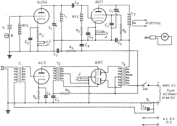
Fig. 1 - Circuit of the 5- and 10-meter transmitter. C1 - 50 μμfd. variable.C2 - 0.005 μfd. mica. C3,C7 - 0.1 μfd. 600.volt. C4 - 100 μμfd. mica. C5 -10 μfd. 50-volt electrolytic. C6 -100-μfd. 25-volt electrolytic. R1 - 20 ohms, 10-watt. R2 - 200 ohms, 2-watt. R3 - 50,000 ohms, 1-watt. R4 - 25,000 ohms, 10-watt. R5 - 15,000 ohms, 10-watt. R6 - 1000 ohms, 1-watt. T1 - Microphone-to-grid transformer.T2 - Single-plate to p. p. grids. T3 - P.P. plates to r.f. load (6000 ohms) B - 2-volt 60-ma. bulb (or larger - up to 200 ma.). X - 10-meter crystal (Bliley). M - 0-100 milliammeter. Sw - S.p.s.t. toggle switch. RFC - 2.1-mh. chokes 125 ma. J - Closed circuit jack. L1 - 6 t. No. 12 wire 3/4" diameter spaced diameter of wire. L2 - Commercial 10-meter plug-in coil. Same for 5 meters. The oscillator plate current runs 20 to 25 ma. when tuned to resonance. Unlike common grid-leak-biased tubes, resonance is indicated by maximum plate current. The final amplifier plate dips to 20 or 25 milliamperes. Since the meter is in the cathode circuit, it reads combined grid, screen grid, and plate current. The grid current of only a few milliamperes is disregarded in the meter reading. With 8-10 milliamperes screen current I find that the drive to the 807 final is sufficient. This results in fairly good efficiency on 10 meters. With antenna or dummy load, it is possible to load up the final to about 55 ma. This results in a power input of approximately 22 watts and an output of about 12 watts. A jack was included in the modulator plate circuit more for convenience than necessity, so that the meter can be used as a volume indicator if desired. The no-signal current runs about 40 ma., while average speech sends the current up to 60 ma. Steady sine wave input for maximum output (100 per cent modulation) runs about 70 ma. While this transmitter was originally designed for portable and portable-mobile use on 5 and 10 meters, it seems not undesirable to have one of these units around the shack for emergency or local rag chews. With the commercial plug-in coils and several crystals, band change can be quickly accomplished. In spite of the difficulties encountered, this little outfit gave much satisfaction in its operation and appearance. I wish to express my appreciation to W8QOG, Queen City Radio Club, for the tests on the signal, Mr. W. Cheshire, W8UPC, and Mr. W. A. Phillips and his associates in the laboratory for their assistance.
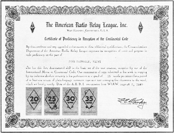
Have you got your code attainment award certificate from A.R.R.L.? This League award is available to every United States amateur li-censed. The program aims to recognize your code ability. WIA W prac-tice transmissions take place on 1761, 3825, 7280, 14,253 and 28,510 kcs. daily except Friday starting at 9:15 p.m. C.S.T. These will help you add to your ability to read code the knack of copying code. It is time now to prepare for the next official qualifying run from WIAW which will take place Friday, February 21st at 9:30 p.m, C.S.T. Aim to get your certificate or endorsement sticker for higher speed on that date.
October 13, 2021 |
|||||||||||||
 |
|||||||||||||
|
|||||||||||||


|
||||||||||||||||||||||||||||||||||||


