|
June 1947 Popular Science
 [Table of Contents] [Table of Contents]
Wax nostalgic about and learn from the history of early
electronics. See articles from
Popular
Science, published 1872-2021. All copyrights hereby acknowledged.
|
Do you remember when the
musical greeting cards with the integrated microchip and speaker for playing a jingle
first appeared in stores like Hallmark? They, along with cards having flashing
LEDs were showing up in display racks sometime around 1990, and cost about $10
(~
$24 in today's money). The sound quality was low, but its novelty overrode
the tinny, digital timbre. This 1947 article from Popular Science had
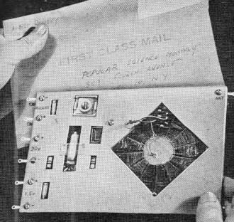
what might have been the world's first mailable electronic greeting card. It did
not have a programmed integrated circuit onboard, but did incorporate a complete
AM radio circuit, including a "peanut" tube for amplification. Unlike modern
musical cards that have an onboard coin cell for power, this one required the
recipient to connect his own "A" (1.5 V) battery and "B" (22.5 V) battery to get
it working. He would also need a set of headphones as there was no built-in
speaker (see photo). Still, it was a novel and intriguing concept at the time,
demonstrating the advance in component miniaturization in the day. I don't
recall seeing advertisements in my many hundreds of vintage electronics and
technology magazines pitching electronics greeting cards, so I'm guessing the
idea never made it to the commercial market phase.
One-Tube Radio Can Be Mailed

Fitting parts into slots in the cardboard chassis makes the set flat and also
guards the components.

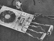
Small crocodile clips soldered to the various detachable leads permit quick and
easy connection.

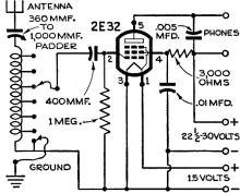
Resistors are 1/4 watt, and the tubular condensers 200 volts; phone impedance
should be 2,000 ohms.

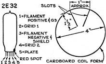
Tube leads may be identified by the position of the red spot. The coil is wound
on a cardboard circle.
By Albert Rowley
Subminiature tubes measuring less than 1/4" in diameter will make it possible
to redesign radio circuits to almost any shape and size. This novelty receiver is
as flat as the tube itself and can therefore be inserted in a 6" by 9" envelope
and sent through the mails as a letter. The two pieces of 1/8" cardboard that form
the chassis are held together by the same nuts and bolts that hold the phone, battery,
antenna and ground terminals in place. Slots are cut in the cardboard to clear the
components.
The tiny 2E32 tube is a shielded pentode and operates with a plate voltage of
22 1/2 and a filament voltage of 1 1/4. For the latter, a small flashlight cell
will give several hours of useful life. One of the miniature 22 1/2- or 30-volt
batteries will supply both the plate and the screen.
To keep the receiver flat, the coil is wound on a cardboard disk 4" in diameter.
Cut 13 slots at intervals of approximately 1" as shown in the sketch below; then
interlace the form with 92 turns of No. 30 enameled wire. At every twelfth turn,
make a tap by scraping the enamel and letting a drop of solder adhere to the spot.
Although the circuit doesn't employ regeneration, it has sufficient power to
pull in local stations. By selecting the right antenna and ground taps and adjusting
the trimmer in the antenna lead, it should be possible to cover the entire broadcast
band. The trimmer specified in the drawing is intended for use with a short indoor
antenna; if used with a long antenna, a trimmer of lower capacity - say 125 to 350
mmf. - should be substituted.
Posted January 5, 2024
|


