|
|||||||||||||
 |
|||||||||||||
Understanding Transistor Circuits
|
|||||||||||||
It had been only a little over a decade since the transistor was invented when this article appeared in the August 1959 edition of Popular Electronics. Transistors were still a mystery to most people, including engineers, technicians, and hobbyists. Author James Butterfield takes a unique approach in presenting the material by writing it as a dialog between an instructor and a student. If you are also new to transistors, this will be worth your while to read. The basics will never change. As an aside (and mentioned in the article), while still a technician I had a manager one time who actually told an engineer working for him that a transistor could be made by soldering two diodes together and using the center node as the base connection. Understanding Transistor Circuits A common-sense guide to using transistors
By James Butterfield Canadian National Telegraphs Part 1: Ohm's law and the Transistor Pete introduces Johnny to the grounded emitter circuit. Its "why's" and "how's" are investigated and the not-too-mysterious matters of base and collector bias are discussed. The rule is, as Pete explains it, "Let Ohm's Law be your guide." Part 2: Design "Do's" and "Don'ts" Trying to design a one-transistor amplifier, Johnny gets tangled up with input and output impedance problems. Pete straightens him out with some important "do's" and "don'ts" in getting a signal in and out of a transistor. Part 3: Controlling, Coupling. and Testing The transistorized approach to filters and tone and volume controls is detailed by Pete with some practical suggestions on the testing of transistor characteristics. Coupling problems are discussed, and Pete draws up a chart that matches the coupling capacitor to the collector resistor Ohm's Law and the Transistor
"That's an amplifier?" snorted Johnny. "You must have dreamed up that circuit during a fit of indigestion! Anybody knows even the simplest transistor amplifiers are bristling with resistors and oversize coupling capacitors. And where's the output transformer for the speaker?" "Don't need any." Pete clipped on the ground lead from the audio generator and inserted a .1-µf. capacitor in series with the other lead. "Trouble with most of you experimenters is that you just copy diagrams - maybe change 'em a little here and there to see what happens - but you never bother to find out what really makes things tick." He touched the other end of the capacitor to his input lead, and the speaker sang with a clear tone. "Pete, I've got six books on transistors, and I still don't know what I'm doing," complained Johnny. "They are either so simplified that they don't say anything - or they're crammed with equations from stem to stern," "Nothing wrong with equations." Pete was busy tidying up his workbench. "But you don't always need 'em. I threw this amplifier together without fancy calculations - just horse sense. Let's go into the kitchen for coffee, and I'll try to fill you in on the practical side of transistors." Diodes Back to Back
"The way I've shown it here, the transistor is a p-n-p unit. To get an n-p-n job, you flip both diodes end-for-end. We'll dig deeper into this later-but for now, just remember when positive voltage is on the p section and negative voltage on the n section, the transistor conducts." "I suppose the lead in the middle is the base," said Johnny. "But which is the collector and which is the emitter? Your diagram doesn't show any difference." "Here's something that will probably surprise you, Johnny. The collector and the emitter could be changed around and the transistor would still work! But since the manufacturer normally builds the collector bigger and stronger than the emitter - take his advice and use the collector lead as the collector. "The real difference between the collector and emitter is in the way we treat them. The emitter is biased to allow maximum current flow (forward bias) and the collector, on the other hand, is back-biased for minimum current."
"Right, Johnny, there's seldom more than a quarter of a volt difference between emitter and base, which makes it easy to figure emitter current. Take this circuit for example: "The collector isn't important just for the moment, so I won't show any wiring to it. Since the emitter is at ground, you can figure that the base is almost exactly at ground, too. This means ..." "I get it," cried Johnny. "The battery puts exactly three volts across the 1500-ohm resistor, so Ohm's law says that the current must be ... ah ... two milliamps !"
"Negative voltage on the base, and positive on the emitter ... so the transistor must be a p-n-p!" exclaimed Johnny triumphantly. A Current Problem "Now, here's point number two. The collector must be biased in the non-conducting direction. How would you do that?" "Put negative voltage on it, I suppose," said Johnny thoughtfully. "But, wouldn't that mean that no current would ever flow?"
"Now you're getting complicated," complained Johnny. "You sound like a textbook." "Okay, let's put it this way. Whatever current flows through the base will produce an amplified current through the collector. You know how to find the base current - we just did it by Ohm's law. So you take the base current (Ib), multiply it by your amplification factor (Hfe) - and there's Ic, your collector current."
"Not at all! Ignoring the fine points, Ic will always equal Ib x Hfe. The latest G.E. transistor manual, by the way, lists Hfe for over four hundred transistors of all makes. "The experimenters' transistors, such as the 2N107 and the CK722, have gains of about 20. Commercial grade transistors can run gains as high as 100 or more. "Let's take a look at another circuit," Pete continued, sketching rapidly. "See what you make of this."
"Nope," said Pete cheerfully, "with one exception. What would happen if that resistor were, say, 2000 ohms?" "Well ... Ohm's law says that two milliamps times 2000 ohms makes a drop of four volts. Oh, I see what you're getting at. If your collector resistor is too big, it won't pass any voltage ... " "And once you lose the voltage, you lose your transistor action," finished Pete. "A resistance of about 800 ohms would be dandy for this circuit." "That would give a collector voltage of - let's see - three volts minus a 1.6-volt drop across the resistor leaves a little under a volt and a half for the collector. Isn't that too low? You'd never be able to put out a decent signal voltage with a supply like that." "Depends on what you're using the amplifier for. Usually, you don't need voltage - all you want is current." Beating the Heat "Another thing, Pete, what about heat effects? Are transistors as heat-sensitive as some of my books say? Does the gain change, or what?" "No, the gain of a transistor usually stays fairly steady; but when the thermometer is high, a little leakage current sneaks through. Don't worry about it, though. You'll seldom have trouble if you stay well within the maximum ratings of the transistor." "These 'max' ratings - anything complicated about them?" "Gosh, no! Maximum collector-to-base voltage, maximum collector current, and maximum collector dissipation - that's all you'll have to worry about. They mean just what they say. Don't put too much voltage across a transistor; don't put too much current through it; and don't heat it up too much with a combination of the two. "Now - you've made a start on logical transistor design. The fine points will come later. Whomp yourself up a few circuits. You'll find that theory and practice go hand in hand. Then when you think you've got the basic idea under your hat, we'll dig into this thing a little deeper." Design "Do's" and "Don'ts"
Pete carefully set down his soldering gun and turned toward his visitor. "What seems to be the trouble, Johnny?" "Well ... I wanted to boost the output of the radio I'm using as a tuner. I laid out a circuit the way you showed me, but it doesn't seem to work right. The volume is just as low as before - and what's worse, the tone is mushy and distorted. I tried a new transistor with no better results. Pete, tell me, where did I goof?" Pete grinned. "I think I know what the trouble is, Johnny. Your circuit is probably good for a vacuum tube. You'll have to learn to think in different terms for transistor amplifiers. "First of all," said Pete, reaching for a pencil and scratch pad, "do you remember how I told you that a transistor was really a pair of diodes back to back?" "Yes. I got that part okay."
"Remember that the base-emitter 'diode' must be hooked up to conduct in the forward direction. Let's look at the circuit of an ordinary transistor amplifier. "As I told you last time, in a p-n-p transistor negative voltage is applied to the base and positive voltage to the emitter, and conduction takes place in the diode formed by the base and emitter. I'll sketch this part of the circuit in detail for you. "When a diode conducts, it's just as if a switch has been closed. Now, when this base-to-emitter diode is conducting, all your a.c. signal goes directly through the diode to ground. For most purposes, the input impedance is so low that you can consider it zero." "Just a minute," interrupted Johnny. "If the input is a short circuit, how can you get any amplification? There won't be any voltage left at the input if you short it all out." "Forget about voltages. Here's the important thing. Since the transistor has a 'short-circuit' input, it may not have much voltage at the input, but current flows into the transistor. Current is what a transistor amplifies.
"Pete, I notice you always put your signal into the base and take your amplified output from the other collector. It seems to me I've heard of other ways of connecting a transistor." "Forget them, Johnny. There are very few jobs that can't be handled by the grounded emitter. We'll talk about the other circuits when an occasion arises that requires their use." Cascaded Amplifiers
"That's not exactly true, Johnny. It depends on how you hook into the transistor output. "Suppose we put the output directly into another transistor stage," continued Pete. "Since the input of this stage is a short circuit, all your signal will be 'shorted' directly to this stage through the coupling capacitor. In other words, all your output goes to the next stage. "If both these transistors have a current amplification of 40, we can do some fairly accurate figuring. An input of 0.5 ma. will produce 20-ma. output. All of this goes to the second stage to be amplified, giving you a final output of 800 ma. - almost a full ampere."
"A little too much current for comfort. To pass that amount of current, even in a power transistor, you'd have to be careful of heat effects. This doesn't just mean mounting your transistors to dissipate heat - it means using special circuits to compensate for heat effects. "For the time being, with the simple circuit we're using, it would be wise to keep your output signal to a quarter of an ampere or less. At this level, you can bring your d.c. bias down to about a third of an amp collector current, which is well within safety limits for a low collector voltage. If you use more than a couple of volts on the collector, keep an eye on your power ratings. And use a heat sink, of course."
"You could do that, but you'd waste a lot of power. The easiest way to do it is to put the speaker directly in series with the collector, like this. But if the collector load is too small, there won't be enough voltage drop across it for appreciable power to be transferred to the speaker. Ohm's law, W=I2 R, (where W is the wattage delivered to the speaker, I is the collector current, and R is the speaker impedance) explains the problem. "Get a transformer whose primary matches the collector load requirements and whose secondary fits the speaker, and you're in business." Voltage Out "Let's get back to your original question on figuring your output. If you're using a transistor as a preamplifier for a vacuum tube, you'll have to know your voltage out. This is really very easy when you think about it, because the input of the vacuum tube is usually high enough to ignore.
"Don't tell me!" exclaimed Johnny. "That will be ... ah ... five volts!" "You're sharp this morning. May I point out that if you want to use a transistor in this way - and handle these levels - it would be common sense to put at least seven volts or so on the collector?" "I see what you mean, Pete. And I suppose it would also be a good idea to have at least one milliampere of d.c. current through the collector?" "Right. Remember, of course, that a milliamp of a.c. will draw almost 1.5-ma. peak current, so you should allow a little extra. And that's just for pure sine waves - when you're figuring in terms of average music levels, leave lots of room for swing. "Generally, it's best to choose your d.c, bias currents keeping in mind the a.c. signal voltages you want to handle," Pete went on. "And usually it's best to have at least 1 ma. of collector current, even at low levels. The reason for this is complex, having to do with impedances and distortion. We'll save this topic for another time." N-P-N or P-N-P
"If you use both types together, one emitter goes to positive ground - that's the p-n-p - and the other emitter will go to your negative voltage supply. This is quite okay, since they are connected together signal-wise through the filter capacitor, making both emitters 'grounded.' "Your bias currents are easy to set up on any of these stages. I've left the base and collector resistors unmarked, for two reasons. First, the size of these resistors depends on the battery voltage you are using. And, second, it will do you good to work out the values yourself using the techniques I showed you before." Getting the Signal In
"Across the volume control. I wanted to be able to turn the volume on the radio down and still feed my hi-fi." "Well, let's sketch out a typical receiver circuit. Notice that the detector is designed to work into a very high resistance ... " "I see !" exclaimed Johnny. "The transistor booster would short out the volume control, and put a heavy load on the detector circuit. Well ... how can I get the input impedance high enough so that it won't affect the circuit?" "That's a story in itself, Johnny. The best way is usually to put a resistance in series with your input. But even though your radio isn't an a.c./ d.c. job, you'll probably have hum problems if you try using a common ground. For the moment I'll say this: the best way will probably be to use an input transformer that matches from 500K down to about 100 ohms. "In the meantime, dust off some of those old transistors and see if you can put them to work. A lot of design 'failures' result from the experimenter forgetting to take into account the very low impedance of transistors. "Look me up when you've digested this session and I'll show you how to check out some of the transistor design parameters, and incidentally how to check out some of the transistor design parameters, and incidentally how to test the little gadgets."
It was a week later that Johnny once again sauntered down the stairs into Pete's basement workshop. Pete looked up from a small amplifier he was wiring. "How's tricks, Johnny?" "I'm just a little confused, Pete. All this dope you've been giving me on transistors is hard to digest so fast. For example, you said that the input is a short circuit. Well, the Radio Amateur's Handbook has a table of specs for quite a few transistors, and for the 2N107 they say ... " "They told you the input impedance was around 600 ohms, I bet. Well, in a sense we're both correct. Here, Johnny, look at it this way - you've done a fair amount of wiring. How much resistance would you say there is in hookup wire?" "I never thought about it. Oh ... maybe a half an ohm a foot ... but it doesn't make much difference to the circuit." "Why not?" demanded Pete. "Because even if the resistance were as high as an ohm or two, it's usually so much smaller than any other resistance in the circuit that you don't count it. Who cares about half an ohm or so when you're dealing with resistors of several thousand ohms?" "Right you are, Johnny. And the same thing goes for your question about a transistor input impedance. Even at six hundred ohms, it's so much smaller than any other resistance in the circuit that you can count it as a short." Short and Simple
"But wouldn't that make your calculations inaccurate? You couldn't get the exact values of gain. You'd have to be a few percent off." "Look at it this way, Johnny. To begin with, transistors are never rated exactly. A transistor with a rated gain of 20 might have an actual gain as low as 10 or as high as 40. So, fancy calculations usually aren't worth the trouble." Johnny nodded. "True. But let me draw you a circuit. Now, if the voltage supply were very low - such as a single dry cell - then the collector resistor R would have to be small enough so that it didn't drop all the battery voltage. Wouldn't that mean ... ?" Pete chuckled. "Johnny, you're too sharp for me today. Yes, that would mean your small collector resistor would prevent some of the signal from getting to the next stage. Not only would amplification be poor, but the low resistance would call for some mighty hefty coupling capacitors. And to put another fly in the ointment, as soon as your signal began to get lost in the resistor, distortion would increase sharply. But don't worry - unusually low voltages are almost the only cause of such a situation." "Pete, you lost me. I guess I still don't dig this whole low impedance input idea." "You've been brainwashed by vacuum-tube theory, Johnny - you've got to learn to rethink the problems. Let's look at some volume controls." Volume Control
"If you run into volume control problems such as distortion at low volume, abrupt changes in volume as you move the control, or just excessive noise from the control, check to make sure that you're not goofing up the bias in some way and that there isn't too much current flowing through the control." Capacitors - Filtering and Coupling
"We'll redraw the circuit for transistor use like this. It could function as a scratch filter or a simple equalizer for a magnetic phonograph cartridge. The values, of course, depend on the use." "Could I put two filter sections together, like this?" asked Johnny. "You sure could. That will give you a sharper frequency cutoff." "Looks like all you have to do to adapt a vacuum-tube circuit for transistors is turn it end for end."
"Speaking of capacitors, Pete, I've been meaning to ask you: how do you figure the size of your blocking capacitor?" "Match it to your collector resistor, usually. You know the formula - it goes, 'C equals over ... " "Ouch! Spare me those formulas!" "Tarnation!" grumbled Pete. "If you ever want to get anywhere in electronics, you'll have to start using formulas. Things are getting too complicated for anyone to get along with a wet finger and a screwdriver. "This time I'll give you a break. Here's a table for you. I've rounded off the values for a frequency response down to about 20 cycles." Test Techniques Johnny looked at his watch. "Pete, I'll have to run soon. But first, you told me last time that you'd give me the low-down on how to test transistors." "Well, it's fairly easy. A nice thing about transistors is that they usually don't gradually deteriorate-they burn out. And you can spot almost all faults real quick by two simple tests: leakage and gain.
"Just how do you make these tests, Pete?" "Easy. Let's take leakage. If I leave the base of a transistor disconnected, current can't flow through the other two leads. The transistor is just two diodes, back to back; so one of them will block the current flow. "Practically, this isn't quite true. A small leakage current will flow - usually less than a tenth of a milliampere for most low and medium power transistors. A reading over 1 ma. means your transistor has 'had it'. "So, to test for leakage, just place about six volts across the emitter and collector, using the normal polarity for the transistor type. A milliammeter with a range of anywhere from 1 - 10 ma. will do the trick. And for the protection of the meter, it's a good idea to add a 2000-ohm series resistor. This won't affect the accuracy of the test. "Testing for gain is just as simple. Think back to our first talk. Whatever current is put into the base of a transistor appears multiplied by the amplification factor (beta) in the collector circuit." "Of course," exclaimed Johnny. "All you have to do is put a milliammeter in the base circuit, another in the collector circuit - and you can see your amplification !"
"If a transistor's beta reads low, don't throw it out. Remember, you're not working with vacuum tubes where low gain usually means that the tube is wearing out. "Power transistors are checked in the same way - but you'll find much more leakage, sometimes as high as 10 ma. Because of this, it's easiest to check this type at much higher current levels. "Transistor testers are quite inexpensive. Kit models are available, and it's a lot easier to build yourself a finished tester than it is to rig up a circuit every time you want to check a transistor. "And another thing. You'd better learn how to use a little math! Those formulas are there to help you. Dust off an old textbook, and ... " "Yes, sir! Just as you say, sir! I'm on my way right now!" Johnny seized the pile of circuit sketches and ran up the stairs. He waved back. "Thanks, Pete. See you later !" 8-Watt Audio Amplifier Driver Stage of the above amplifier is mocked up on this months cover This class B audio amplifier will deliver 8 watts output with less than .5 watt of audio drive. T1's impedance primary is chosen to load the previous stage properly. Collector current in the first stage is set at 70 ma. at a with R1. Pot R2 is adjusted for 100 ma. at b. Both output transistors require the use of large heat sinks for proper operation.
Code Practice Oscillator
Pocket Regen Receiver
R.F. Preamplifier
High-Frequency Xtal Oscillator
Code Keyer
Dynamic Microphone Preamp
Wireless Microphone
Sensitive Photo Relay
Posted March 1, 2021 |
|||||||||||||
 |
|||||||||||||
|
|||||||||||||


 "This should do it," grunted Pete,
as he soldered a final connection. "Now, let's tryout the amplifier."
"This should do it," grunted Pete,
as he soldered a final connection. "Now, let's tryout the amplifier."  "First off," said Pete settling in a chair,
"You know that a transistor is sort of like a pair of diodes, back to back,
like this." He sketched rapidly on a napkin.
"First off," said Pete settling in a chair,
"You know that a transistor is sort of like a pair of diodes, back to back,
like this." He sketched rapidly on a napkin.  "Hey," Johnny cut in. "Wouldn't a heavy
current flow from the base through the emitter mean that there would be darn
little voltage drop between the emitter and base?"
"Hey," Johnny cut in. "Wouldn't a heavy
current flow from the base through the emitter mean that there would be darn
little voltage drop between the emitter and base?"  "Bravo!" chuckled Pete. "And since this
part of the transistor is conducting in the forward direction, the current will
not be affected by the collector. By the way, what type of transistor did I
show in the diagram?"
"Bravo!" chuckled Pete. "And since this
part of the transistor is conducting in the forward direction, the current will
not be affected by the collector. By the way, what type of transistor did I
show in the diagram?"  "That would be true if the collector and
base only were connected," replied Pete. "But when the emitter is in the circuit
with positive bias, an interaction allows current to flow through the collector."
"That would be true if the collector and
base only were connected," replied Pete. "But when the emitter is in the circuit
with positive bias, an interaction allows current to flow through the collector."
 "Just a minute," argued Johnny. "Suppose
I put a higher voltage on the collector. Wouldn't that make more current flow?"
"Just a minute," argued Johnny. "Suppose
I put a higher voltage on the collector. Wouldn't that make more current flow?"
 "Let me see," murmured Johnny. "With the
emitter grounded, the base has to be at almost zero volts - which will cause
the battery's three volts to drop across the 33,000-ohm resistor. That would
give about 0.1 ma. flowing through the base. If the amplification of the transistor
is 20, that means the collector will take almost two milliamps. But, doesn't
the size of resistor R make any difference to the collector current at all?"
"Let me see," murmured Johnny. "With the
emitter grounded, the base has to be at almost zero volts - which will cause
the battery's three volts to drop across the 33,000-ohm resistor. That would
give about 0.1 ma. flowing through the base. If the amplification of the transistor
is 20, that means the collector will take almost two milliamps. But, doesn't
the size of resistor R make any difference to the collector current at all?"
 "Pete, I've been playing around
with transistors like you told me, and I've got problems."
"Pete, I've been playing around
with transistors like you told me, and I've got problems." 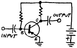 "Fine. Now let's go back to fundamentals
again and attack the problem from a different position.
"Fine. Now let's go back to fundamentals
again and attack the problem from a different position.  "Suppose we have a transistor with a beta
- that's current gain - of 20. Then if I put one milliampere of signal into
the base, I'll get 20 ma. at the collector. Write this in your notebook in capital
letters an inch high - A TRANSISTOR AMPLIFIES CURRENT."
"Suppose we have a transistor with a beta
- that's current gain - of 20. Then if I put one milliampere of signal into
the base, I'll get 20 ma. at the collector. Write this in your notebook in capital
letters an inch high - A TRANSISTOR AMPLIFIES CURRENT."  "Pete, how do I go about using an output
that's rated in milliamps instead of volts? The current goes through the collector
resistor, so it can't be used as it stands."
"Pete, how do I go about using an output
that's rated in milliamps instead of volts? The current goes through the collector
resistor, so it can't be used as it stands."  "Wow!" Johnny exclaimed. "That's a lot of
current!"
"Wow!" Johnny exclaimed. "That's a lot of
current!" 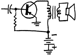 "Pete, I still don't see how we're going
to use that final output current. Do you connect a coupling capacitor to the
speaker or what?"
"Pete, I still don't see how we're going
to use that final output current. Do you connect a coupling capacitor to the
speaker or what?"  "In this diagram, the total transistor load
is the 5000-ohm collector resistor shunted by a 1/2-megohm volume control. For
all practical purposes, our output load is 5000 ohms. If our design shows we
have a signal current of one milliampere on the collector, we use Ohm's law
..."
"In this diagram, the total transistor load
is the 5000-ohm collector resistor shunted by a 1/2-megohm volume control. For
all practical purposes, our output load is 5000 ohms. If our design shows we
have a signal current of one milliampere on the collector, we use Ohm's law
..."  "You've probably noticed that all the transistors
I've shown have been p-n-p types. As far as signal amplification goes, n-p-n
transistors are exactly the same. Your signal goes into the base and comes out
from the collector. Your connections for bias will be different, but that won't
affect your signal.
"You've probably noticed that all the transistors
I've shown have been p-n-p types. As far as signal amplification goes, n-p-n
transistors are exactly the same. Your signal goes into the base and comes out
from the collector. Your connections for bias will be different, but that won't
affect your signal.  "Let's discuss the booster you tried your
hand on, now. Where did you connect the transistor?"
"Let's discuss the booster you tried your
hand on, now. Where did you connect the transistor?"  Controlling, Coupling and Testing
 "It's very simple to figure out a circuit
this way, too. Using the short-circuit input approach, you eliminate most of
the calculating."
"It's very simple to figure out a circuit
this way, too. Using the short-circuit input approach, you eliminate most of
the calculating." 
 "A vacuum-tube circuit volume control transferred
to a transistor circuit would look like this. Whereas a tube draws almost no
grid current, the base input of the transistor does - and right through the
control. You can see how moving the "pot" arm up and down is not only going
to tap off a part of the signal current, which is what we want it to do, but
unfortunately it's also going to change the value of the base bias resistor.
A volume control with no problems looks like this.
"A vacuum-tube circuit volume control transferred
to a transistor circuit would look like this. Whereas a tube draws almost no
grid current, the base input of the transistor does - and right through the
control. You can see how moving the "pot" arm up and down is not only going
to tap off a part of the signal current, which is what we want it to do, but
unfortunately it's also going to change the value of the base bias resistor.
A volume control with no problems looks like this.  You'll find that transistor filter circuits,
too, have to be approached differently," Pete continued. "Here's a typical tube
low-pass filter. A transistor input following the filter would short out the
capacitor, making it useless.
You'll find that transistor filter circuits,
too, have to be approached differently," Pete continued. "Here's a typical tube
low-pass filter. A transistor input following the filter would short out the
capacitor, making it useless.  "That's partly right, Johnny. But it applies
only to coupling circuits between transistors, and it won't always work. Remember
to make the resistances smaller and the capacitances larger than with tubes.
And check out your circuit practically after you work up the design."
"That's partly right, Johnny. But it applies
only to coupling circuits between transistors, and it won't always work. Remember
to make the resistances smaller and the capacitances larger than with tubes.
And check out your circuit practically after you work up the design."  "This makes the transistor easy 'to check
- no fancy testers needed. Just select n-p-n or p-n-p, check for leakage and
current gain ... and that's it !"
"This makes the transistor easy 'to check
- no fancy testers needed. Just select n-p-n or p-n-p, check for leakage and
current gain ... and that's it !"  "You can do it even easier than that," replied
Pete. "With an exact known current in the base, you need only one meter in the
collector, which you can calibrate to read directly in gain, if you wish. The
ratio of the collector current to the base bias current gives you your gain
figure. An open element, of course, gives you a zero - gain reading, as does
a base-to-emitter short.
"You can do it even easier than that," replied
Pete. "With an exact known current in the base, you need only one meter in the
collector, which you can calibrate to read directly in gain, if you wish. The
ratio of the collector current to the base bias current gives you your gain
figure. An open element, of course, gives you a zero - gain reading, as does
a base-to-emitter short. 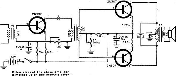
 A transistor version of the Colpitts oscillator
is used here as a code practice oscillator. The 1- megohm tone control may be
adjusted for the most pleasing tone. Ordinary magnetic headphones are used and
serve as an inductance in the oscillator circuit.
A transistor version of the Colpitts oscillator
is used here as a code practice oscillator. The 1- megohm tone control may be
adjusted for the most pleasing tone. Ordinary magnetic headphones are used and
serve as an inductance in the oscillator circuit. 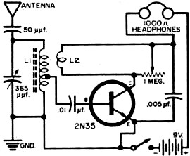 Regenerative detectors are easily adapted
to transistor radio use. In this circuit, coil L1 is a standard transistor antenna
coil and the feedback winding (L2) consists of 10 - 15 turns of wire wound around
the center of L1. The 1-megohm potentiometer is the regeneration control and
should be set just below the point where whistles or "motorboating" are heard
in the headphones. If no regeneration is heard, reverse the connections to tickler
feedback coil L2.
Regenerative detectors are easily adapted
to transistor radio use. In this circuit, coil L1 is a standard transistor antenna
coil and the feedback winding (L2) consists of 10 - 15 turns of wire wound around
the center of L1. The 1-megohm potentiometer is the regeneration control and
should be set just below the point where whistles or "motorboating" are heard
in the headphones. If no regeneration is heard, reverse the connections to tickler
feedback coil L2.  Some of the better broadcast-band receivers
include an r.f. stage for increased sensitivity. Extra r.f. amplification can
be added to almost any receiver without any complicated rewiring by means of
a simple r.f. preamp such as the one shown here.
Some of the better broadcast-band receivers
include an r.f. stage for increased sensitivity. Extra r.f. amplification can
be added to almost any receiver without any complicated rewiring by means of
a simple r.f. preamp such as the one shown here.  Shown above is a general-purpose crystal
oscillator for use at frequencies up to 20 mc. designed around a 2N94A transistor.
Approximately 10 milliwatts of r.f. output are developed at the crystal frequency.
The low-impedance pickup coil (L2) consists of two or three turns wound close
to the lower end of L1. Coil L1 and C1 are chosen to resonate at the crystal
frequency.
Shown above is a general-purpose crystal
oscillator for use at frequencies up to 20 mc. designed around a 2N94A transistor.
Approximately 10 milliwatts of r.f. output are developed at the crystal frequency.
The low-impedance pickup coil (L2) consists of two or three turns wound close
to the lower end of L1. Coil L1 and C1 are chosen to resonate at the crystal
frequency.  Here is a code keyer unit designed to eliminate
the key clicks and thumps that may be cluttering up your transmissions. With
the key up, the transistor is cut off, as is the tube being keyed. With the
key down, current drop across the collector-emitter circuit is about 0.1 volt,
and you're on the air. Before adding the keyer unit to your transmitter, make
these checks. 1. Connect a 20,000-ohm voltmeter across your transmitter
key jack. If the voltage is greater than 25 volts, it may be necessary to reduce
the screen voltage on the keyed tube to 150 volts or less. Use a voltage-regulated
supply or voltage-divider network rather than a simple series resistor. 2.
Measure the current to be keyed by placing a milliammeter across the key. This
current should not be much greater than 50 ma. 3. If it was necessary
to lower the screen voltage, check the r.f. output. If the output is too low,
return the screen voltage to normal and use two complementary transistors in
series back-to-back, as shown in the alternate circuit diagram. Note that the
keyer should never be left in the key-down condition.
Here is a code keyer unit designed to eliminate
the key clicks and thumps that may be cluttering up your transmissions. With
the key up, the transistor is cut off, as is the tube being keyed. With the
key down, current drop across the collector-emitter circuit is about 0.1 volt,
and you're on the air. Before adding the keyer unit to your transmitter, make
these checks. 1. Connect a 20,000-ohm voltmeter across your transmitter
key jack. If the voltage is greater than 25 volts, it may be necessary to reduce
the screen voltage on the keyed tube to 150 volts or less. Use a voltage-regulated
supply or voltage-divider network rather than a simple series resistor. 2.
Measure the current to be keyed by placing a milliammeter across the key. This
current should not be much greater than 50 ma. 3. If it was necessary
to lower the screen voltage, check the r.f. output. If the output is too low,
return the screen voltage to normal and use two complementary transistors in
series back-to-back, as shown in the alternate circuit diagram. Note that the
keyer should never be left in the key-down condition.  Some high-grade dynamic microphones have
too low an output to be used with tape recorders or p.a. systems. A simple self-contained
preamp can be designed using one transistor which will boost the output of these
low-level microphones sufficiently for almost any type of application.
Some high-grade dynamic microphones have
too low an output to be used with tape recorders or p.a. systems. A simple self-contained
preamp can be designed using one transistor which will boost the output of these
low-level microphones sufficiently for almost any type of application.  A miniature hand-held wireless microphone
can be constructed using an r.f. transistor in a Hartley-type oscillator. Good
short-range results can be obtained on the broadcast band with a 2' whip antenna.
Follow the manufacturer's coil terminal numbering shown or oscillation will
not occur. Adjust the coil and trimmer for best reception on a clear spot in
the broadcast band.
A miniature hand-held wireless microphone
can be constructed using an r.f. transistor in a Hartley-type oscillator. Good
short-range results can be obtained on the broadcast band with a 2' whip antenna.
Follow the manufacturer's coil terminal numbering shown or oscillation will
not occur. Adjust the coil and trimmer for best reception on a clear spot in
the broadcast band.  This two-stage direct-coupled circuit offers
high sensitivity in photocell applications. A 1-megohm pot is included for sensitivity
adjustment over a wide range. The relay is a sensitive Advance Type SO/1C/4000D
or equivalent.
This two-stage direct-coupled circuit offers
high sensitivity in photocell applications. A 1-megohm pot is included for sensitivity
adjustment over a wide range. The relay is a sensitive Advance Type SO/1C/4000D
or equivalent. 
|
||||||||||||||||||||||||||||||||||||


