|
|||||||||||||
 |
|||||||||||||
After Class: The Traveling-Wave Tube
|
|||||||||||||
Here is a great primer on the operation of traveling wave tubes (TWT). A controversy exists over who first invented the TWT - Bell Telephone Labs' Dr. Rudolf Kompfner, or Andrei Haeff while at the Kellogg Radiation Laboratory at Caltech. Regardless of its provenance, the device was a major advancement in the development of high power microwaves. A TWT amplifies broadband microwaves continuously: an electron gun emits a high-speed beam through a vacuum tube, interacting with the weak input signal propagating along a helical slow-wave structure. The helix slows the signal's phase velocity to sync with the electrons, whose velocity is modulated by the signal's electric field, bunching them into dense clouds that transfer kinetic energy back to the wave for substantial gain before collector absorption. In contrast, the narrowband klystron velocity-modulates the beam discretely in an input cavity, allows drift bunching, then extracts power in an output cavity for high gain/efficiency. The magnetron oscillates without input: a rotating electron cloud in crossed E/B fields couples to resonant cavities, yielding high power/tunability. After Class: The Traveling-Wave Tube
Ethylene glycol, a chemical obtained as a byproduct in the manufacture of certain synthetics, was once unceremoniously dumped into the waters of the Delaware River. Then someone discovered that it possessed unique anti-freeze properties. The waste disposal chute was promptly diverted from the river into gallon cans which today, under the name of "Prestone," sell for $3.75 each! The same kind of thing has happened in the development of microwave electron tubes. Ordinary triodes and pentodes are very satisfactory amplifiers at medium frequencies, but they begin to misbehave at the ultra-high frequency end of the spectrum. Among the more important causes of this misbehavior is the effect called electron transit time, an effect in which the time required for an electron to travel from the cathode to the plate of a tube is almost as great as the time needed for the r.f. signal to complete one full cycle. This effect renders the tube incapable of "following" the signal frequency, so that it fails completely as an amplifier or oscillator.
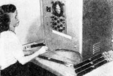
What it looks like. Here, low-level, low-noise traveling-wave tubes are shown undergoing a final check at RCA Tube Division, Harrison, N. J.
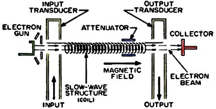
Fig. 1 - Functional diagram showing bask components of a traveling-wave tube amplifier.
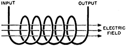
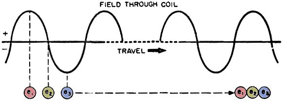
Fig. 2 - To understand how the traveling-wave tube operates, keep in mind that a u.h.f. wave on the coil produces an electric field.
Fig. 3 - Electrons travel from left to right, but they are bunched together due to the field in the coil. See text. Like the man with the anti-freeze inspiration, ingenious electronic engineers have designed microwave tubes which actually make use of the transit time effect in generating and amplifying frequencies so high in the spectrum that they approach the wavelengths of light. Now, instead of preventing microwave operation, electron transit time phenomena enable us to work with frequencies higher than 50,000 megacycles! The traveling-wave tube is an example of such an application. One can hardly scratch the surface of microwave techniques without coming upon this tube or others like the klystron and magnetron. Basic Parts All traveling-wave tube amplifiers incorporate the basic parts shown in Fig. 1. These include an electron gun - such as one finds in the picture tube of a TV set, a "slow-wave" structure - generally in the form of a loosely wound coil, a collector which receives the electron beam at What it looks like. Here, low-level, low-noise traveling-wave tubes are shown undergoing a final check at RCA Tube Division, Harrison, N. J. the other end of the tube, and an attenuator for preventing unwanted oscillations. The electron gun produces a beam of electrons which moves through the hollow center of the coil. It is restricted to a tight beam by a strong magnetic field around the body of the tube (not shown in the diagram). Its velocity is controlled by varying the d.c. voltage between the coil and the cathode of the gun. If nothing more were done, the beam would simply move through the length of the coil in a uniform stream as in Fig. 2 and be returned to the circuit via the collector electrode. But something else must happen if amplification is to be realized. How Wave Travels Imagine that a radio signal of ultra-high frequency - say 20,000 mc. - is applied to the coil. Such a wave travels at a speed approaching the velocity of light - 186,000 miles per second - around the turns of the coil. It does not advance from one end of the tube to the other end of the tube at this rate, however. The actual velocity of propagation of the wave along the axis of the coil is found by multiplying the speed of light by the distance between turns of the coil and dividing the product by the circumference of the individual turns: rate of advance = (velocity of light) x (turn spacing) / (turn circumference) Since the ratio of turn spacing to turn circumference is always a small fraction, the total product is considerably less than the speed of light. While the wave moves around the turns of the coil, it thus produces an electric field through the axis of the coil which moves with this velocity, as shown in Fig. 2. The electric field advances from one end of the tube to the other and, as it does so, an interaction takes place between the moving field and the electron beam from the cathode gun. This interaction results in delivery of energy from the electron beam to the wave from the coil, causing the signal to become larger as the coil's output end is approached. Energy Transfer The electric field moving axially through the coil consists of ultra-high frequency pulsations which alternate into the positive and negative regions. This is illustrated as a wave on the horizontal axis in Fig. 3. Let us consider three electrons, e1, e2, and e3, which belong to the beam passing through the coil, and observe them at the time shown in Fig. 3. At this instant, e1 is in the presence of a positive portion of the field and is therefore accelerated in its motion through the coil. The velocity of electron e2 remains unaffected, however, because it is in a position of zero field strength while e, is decelerated, being enmeshed in a field of negative polarity. This starts a bunching process in which all the electrons in the immediate vicinity of e2 begin to concentrate around this particle, some decelerating while e, catches up with them while others speed up to overtake e3. As the wave continues through the axis of the tube, the bunching action intensifies. This strong concentration of moving electrons induces a second wave in the coil which lags behind the original signal wave. The effect of this lag is to produce a new decelerating action on the electron beam. Amplification At this point we have to draw upon the Law of Conservation of Energy to understand how amplification is produced. Energy can neither be created nor destroyed but only changed in form. Before being decelerated; the electrons in the beam possess a given amount of kinetic energy. Conservation tells us that when they are decelerated the energy these electrons lose must be transferred to the agent which has caused the slow-down. Thus, the electron beam adds some of its energy to the content of the signal, causing the latter to emerge from the output end of the coil larger than it was when it first entered. Hence, amplification has been realized. Our troubles are not yet over, however. Whenever a wave travels through a guiding medium, there are likely to be reflections from the remote end. In the traveling-wave tube, such reflections are prone to start oscillations which, of course, are highly undesirable in an amplifier. This tendency is controlled by introducing an attenuator near the output end of the tube, usually in the form of a coating of graphite inside the glass. This conductive area absorbs energy from the reflections, preventing them from reaching the input end of the tube in sufficient strength to maintain oscillatory feedback. One of the most appealing features of traveling-wave tubes is their ability to amplify all signals over a very wide band of frequencies. Familiar amplifier circuits for radio frequencies usually involve resonant circuits which tend to limit the passband by the very nature of their resonance curves. The traveling-wave tube, being an essentially non-resonant device, is not limited in this manner. A well- designed traveling-wave tube can provide approximately equal amplification over the unbelievably wide band of 2000 mc! |
|||||||||||||
 |
|||||||||||||
|
|||||||||||||
 Special Information on Radio, TV Radar and Nucleonics

|
||||||||||||||||||||||||||||||||||||


