July 1959 Popular Electronics
 Table
of Contents Table
of Contents
Wax nostalgic about and learn from the history of early electronics. See articles
from
Popular Electronics,
published October 1954 - April 1985. All copyrights are hereby acknowledged.
|
Prior to the advent of FET-input
digital multimeters (DMMs), the vacuum tube voltmeter (VTVM) was the primary instrument
for use when high input impedance was required. For the newcomer to electrical measurements,
high input impedance for the measuring instrument is needed when measuring high
impedance circuits so as not to load down the circuit under test and cause an erroneous
result. For instance, suppose you are trying to measure the voltage across a 100 kΩ resistor that is in series with a 50 kΩ and your voltmeter has a 100 kΩ input
impedance. The parallel combination of the two 100 kΩ resistances (resistor and
voltmeter) is 50 kΩ. If the supply voltage is 3 volts, the voltage across the 100 kΩ resistor would actually be 2 volts, but with the voltmeter across it, the reading
would be 1.5 volts. If the input impedance of the voltmeter was 10 MΩ instead, the
parallel resistance across the 100 kΩ resistor would be about 99 kΩ, which would
only introduce a very small error. I'll try to get the previous 5 parts of this
article.
Test Instruments Part 6
The Vacuum Tube Voltmeter (VTVM)Signal Tracing in a Hi-Fi Amplifier
By Larry Klein
Technical Editor
 In checking out the vacuum-tube voltmeter in
the last two installments of Test Instruments, we discovered that one of the most
important reasons for using a VTVM was "sensitivity." In practical terms, the sensitivity
of a measuring instrument determines how it affects the circuit under test. Using
a low ohms/voltmeter in a high impedance circuit is like trying to gauge a person's
strength with a 10-ton weight. What you're trying to measure crumbles under the
load. In checking out the vacuum-tube voltmeter in
the last two installments of Test Instruments, we discovered that one of the most
important reasons for using a VTVM was "sensitivity." In practical terms, the sensitivity
of a measuring instrument determines how it affects the circuit under test. Using
a low ohms/voltmeter in a high impedance circuit is like trying to gauge a person's
strength with a 10-ton weight. What you're trying to measure crumbles under the
load.
One area where the VTVM comes into its own is in signal voltage measurement in
hi-fi amplifiers. For not only can the VTVM measure the a.c. signal voltage without
knocking it to its knees, but it will perform the measurement in the presence of
d.c. at any frequency in the amplifier's range. If there's a large enough signal
at a tube pin - your VTVM will read it.
What's so important about signal voltage? Well, signal voltage is what your magnetic
phono cartridge (or tape head or tuner) supplies to your amplifier to be passed
on to your speaker. Your amplifier is not just a passive element, but is more like
an electronic Charles Atlas that builds up the weakling input signals into the sort
of powerful currents that can move, if not mountains, at least speaker cones. If
we take a look at the signal voltage at each stage of its development, we can get
a good idea of exactly what contribution is made by each tube in the circuit.
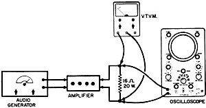 Fig. 11 - Interconnections between test
instruments and amplifier when making gain and wattage checks.
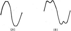
Fig. 12 - Slight (A) and extreme (B) clipping which occurs when output stage
of amplifier is overdriven.
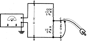
Fig. 13 - Voltage divider set-up which can be used to supply a signal in
the millivolt range to amplifier under test.
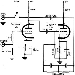

Fig. 14 - Eico HF-12 amplifier circuit broken down into its separate sections
for the purpose of discussion in the text. Reading from top to bottom, sections
are: preamplifier, tone control and power amplifier.
The amplifier we will work with - the Eico HF-12 - is not only well designed
but, in addition, has the advantage for us that it shares a number of its circuit
configurations with amplifiers of similar and higher wattage. The same tests and
techniques we use to check out the Eico unit can therefore also be applied to other
mono and stereo amplifiers.
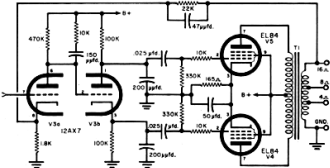
Let's take a quick look at the HF-12's schematic in Fig. 14. The preamp
stage uses a 12AX7
tube (V1) with plate-to-grid feedback equalization. The two triodes of a 12AU7 tube
(V2) comprise the Baxandall negative feedback tone control circuit which in turn
feeds a modified Williamson-type power amplifier comprising a dual-triode driver/inverter
(V3) and a pair of push-pull pentode outputs (V4 and V5).
For the tests we have in mind, we'll need a VTVM and an audio oscillator. Any
of the small fixed-frequency transistorized sine-wave generators will do for gain
tests, but for tone control check-out a variable frequency audio generator such
as the Heath, Eico, or Knight-Kit units is required.
First, the test instrument setup. A vital item in our check-out procedure is
a 16-ohm "load" resistor connected across the amplifier's 16-ohm output terminals.
Since the Eico at full output will throw a good 12 watts into the load resistor,
we better use one with at least a 20-watt rating - and expect it to get pretty hot.
Several series/parallel resistors will do as well as a single wire-wound job as
long as the resistance and wattage demands are met.
Set up the amplifier with the tone controls at flat, volume control on full,
and the selector switch to Aux. Do not plug the amplifier in yet.
Watts = E2/R. Switch on the audio generator and set
it up for 1 kc. with the output control at minimum, and the output lead plugged
into the amplifier's Aux. input.
Set your VTVM to the 15-volt, a.c., or higher range, and connect the test leads
across the 16-ohm load resistor. Now plug in the amplifier, let it warm up, and
slowly turn up the output level of the audio generator.
Watch the VTVM meter needle climb up scale - when it reaches about 14 volts,
we know the amplifier is putting out a healthy 12 watts. How do we know? Ohm's law
tells us so - using the formula: W=E2/R; where E is the voltage developed
across the 16-ohm (R) load resistor and W, of course, is watts output.
If available, an oscilloscope can be used to monitor the output waveform of the
amplifier by connecting it across the load resistor. At about the 5-watt level,
a good-looking sine wave will be seen on the scope. Pushing the amplifier to the
12-watt level (by boosting the input signal voltage), the scope will begin to show
"clipping" as in Fig. 12(A) Boost the input voltage even more, and a waveform
resembling Fig. 12(B) results.
At any rate, just barely visible clipping, all other factors being equal, usually
corresponds to about 1% harmonic distortion. This test is used by a number of manufacturers
to rate the power output of their amplifiers.
Now that we've determined how to get the twelve watts out of the amplifier, let's
use our VTVM to trace the signal from the input through the jungle of resistors
and capacitors which make up an amp's "works."
Stage By Stage. If we want to start our tracing at the high
gain input of the amplifier, we will have to feed in a signal in the 5-10 millivolt
range. If your audio generator lacks an attenuator switch, the circuit shown in
Fig. 13 will take a one-volt signal and knock it down to approximately 10 millivolts.
Use your VTVM to set the A-B voltage and trust to the attenuator for the correct
C-D output voltage.
Set up the amplifier's controls as before, but set the selector switch at the
"mag. phono" position and plug the lead from the attenuator setup into the mag.
phono jack Turn up the audio generator's output, using your VTVM to monitor the
output wattage across the 16-ohm load resistor.
When the VTVM hits 14 volts (about 12.5 watts), transfer the VTVM leads across
A-B on the attenuator. On the Eico, if everything is going well, the VTVM should
indicate anywhere from 0.4 volts to slightly less than 1 volt. An exact reading
can't be quoted because there are just too many variables for on-the-nose results
to be expected.
What have we achieved with the preceding test? Well, with one quick measurement,
we've ascertained that the complete amplifier's sensitivity and power output are
both up to snuff.
If you want to make individual stage gain measurements, use a slight variation
in technique. Keeping the same input signal at mag. phone, as used for the overall
wattage check, take a measurement at the grid of V2A. With your VTVM set for the
lowest a.c. scale, expect about 0.5 volt. Remember, we applied about .005 volt (5
mv.) to the mag. phono input; now, at the output of V1, it's paying off to the tune
of 0.5 volt. A little calculation will reveal that we've achieved a gain of 100
on our investment.
Stage gain measurements in the remainder of the circuit are as simple - but don't
expect the tube manual to be a reliable guide to the gains to be expected. Remember,
negative feedback is used throughout the better hi-fi amplifiers and cuts down gain-per-stage
considerably. For example, in the tone control stage, with 0.5 volt from the preamp
applied to the input grid of V2A, less than 1.5 volts of signal will be found at
the plate of V2B - a gain of somewhat less than 3 for both triodes.
At V3, we come to the direct-coupled voltage amplifier/phase inverter stage.
About 1.4 signal volts applied at pin 7 of V3 will get you 8 signal volts at its
plate - a gain of less than 6.
A Balanced Diet. When the 8 volts of signal are fed to the grid
of the split-load phase inverter (V3B), signal voltages are developed across both
the plate and cathode resistors. The voltages (about 7.75) should be exactly equal
and opposite (180° out of phase).
The push-pull signal developed here feeds the output tubes their balanced diet.
Unequal signals at the plate and cathode (which will cause "upset" in the output
stage in the form of distortion) are usually due to mismatch in the plate and cathode
load resistors. Optimally, they should measure within 1% of each other.
This has been a fast guided tour following a signal through a typical amplifier.
Of course, there are many more specialized measurements the VTVM can make in amplifiers
as well as other equipment. Anywhere that sensitivity and wide frequency response
are important, you'll find the VTVM ready and able to do its part.
Posted October 17, 2022
(updated from original post on 1/13/2012)
|


